EP0267440A1 - Analogous clock with two motors having a perpetual day counter - Google Patents
Analogous clock with two motors having a perpetual day counter Download PDFInfo
- Publication number
- EP0267440A1 EP0267440A1 EP87114859A EP87114859A EP0267440A1 EP 0267440 A1 EP0267440 A1 EP 0267440A1 EP 87114859 A EP87114859 A EP 87114859A EP 87114859 A EP87114859 A EP 87114859A EP 0267440 A1 EP0267440 A1 EP 0267440A1
- Authority
- EP
- European Patent Office
- Prior art keywords
- signal
- date
- circuit
- month
- counter
- Prior art date
- Legal status (The legal status is an assumption and is not a legal conclusion. Google has not performed a legal analysis and makes no representation as to the accuracy of the status listed.)
- Granted
Links
Images


Classifications
-
- G—PHYSICS
- G04—HOROLOGY
- G04G—ELECTRONIC TIME-PIECES
- G04G19/00—Electric power supply circuits specially adapted for use in electronic time-pieces
- G04G19/10—Arrangements for supplying back-up power
-
- G—PHYSICS
- G04—HOROLOGY
- G04C—ELECTROMECHANICAL CLOCKS OR WATCHES
- G04C17/00—Indicating the time optically by electric means
- G04C17/005—Indicating the time optically by electric means by discs
- G04C17/0058—Indicating the time optically by electric means by discs with date indication
- G04C17/0066—Indicating the time optically by electric means by discs with date indication electromagnetically driven, e.g. intermittently
Definitions
- the present invention relates to an analog electronic watch comprising two motors, the first motor driving the time display and the second motor displaying the date. It relates more particularly to a watch further comprising a perpetual calendar circuit.
- This circuit includes day, month and year counters and supplies a signal representing the date to a control circuit which activates the second motor by advancing it by the number of steps necessary so that the indication of the date corresponds to the content of the day counter and therefore be in accordance with the indication of a perpetual calendar.
- Such watches are well known and an exemplary embodiment is described in US Pat. No. 4,300,222.
- the watch described in this document is provided with a perpetual calendar displaying the date and, possibly, the day of the week. If the calendar does not raise any criticism as long as the watch functions normally, on the other hand, after a change of battery, the counters putting themselves in states having no relation to the date, the calendar circuit is no longer able to provide correct signals.
- the counters and the date display must therefore be set, as well as, of course, the time of the watch.
- the correction operation of the date display is done conventionally.
- setting the meters is hardly achievable by the user, nor by a watchmaker who does not have adequate equipment.
- each counter in order to reduce the duration of operations, each counter must be corrected separately, which implies complex manipulations.
- to carry out this correction it is necessary to know the content of the counters. However, this information does not appear on the watch display.
- the battery change can only be carried out in the factory or in an after-sales service center, which constitutes a major constraint in the use of a watch which is otherwise very practical.
- the object of the invention is to overcome this drawback by proposing a watch whose perpetual calendar requires, after replacing the battery, only a correction of the date display using simple manipulation, which can be made by the wearer of the watch.
- the watch according to the invention comprising: - a timepiece circuit providing a time base signal and a fast forward signal having a frequency higher than that of the time base signal; - a first motor activated from the time base signal; - a daily contact activated by the first motor at the end of each day to provide a daily signal; - an analog display of the time driven by the first motor; - a correction device which can occupy a neutral position and a correction position in which it makes it possible to modify the indications of the time display; - Means coupled to the correction member and providing a logic positioning signal, one level of this signal being representative of the neutral position of this member and the other level of the correction position; - a perpetual calendar circuit comprising day, month and year counters, connected in series and activated by the daily signal, and means responding to the state of the month and year counters to set, at the end months of 31 days, the day counter in the state corresponding to the first day of the following month, in which state the day counter provides a monthly signal
- An advantage of the present invention comes from the fact that after a battery change, provided that it is carried out within one month from the date of stopping the watch, it is sufficient to conventional calendar watch, so that the perpetual calendar circuit functions again correctly.
- Another advantage of the invention is that it does not require memorization, every 24 hours, of the content of the day counter in the non-volatile memory, this making it possible to reduce the surface of this memory, to reduce its consumption and d 'increase its lifespan.
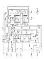
- FIGS. 1, 2 and 3 show the diagrams of an embodiment of the circuit of the watch according to the present invention, the references a, b, c ... m indicating the connection points between the conductors passing from one figure to another.
- timekeeping circuit 1 which provides a time base signal S1 to a first motor 2 which, by means of a control mechanism 3, causes a time display 4 comprising hands hours, minutes and seconds.
- the timepiece circuit 1 includes an oscillator 10 providing a signal of 32,768 Hz for example, frequency stabilized by a quartz resonator 11, an ET12 gate with two inputs, one input being connected to the output of the oscillator, a divider 13 whose input is connected to the output of the ET12 gate, an ET104 gate with two inputs, an input being connected to an output of the divider delivering a signal of 1 Hz, and a drive circuit 14 receiving carries ET104 the signal of 1 Hz and providing at its output the signal S1.
- the frequency divider 13 also has an e output which delivers a fast forward or catch-up signal S13 having a frequency of the order of 10 Hz, and a reset input R which makes it possible to reset the last stages of the divider, located after the stage providing the signal S13.
- This input R is connected to the output of an inverter 15 whose input is connected to the second input of the gate ET12.
- the first motor 2 is, for example, of the stepping type with a direction of rotation, or unidirectional. It drives, in the mechanism control 3, a first gear train, not shown, which advances the hands of display 4. This same gear train also actuates a daily contact X, or first contact, closing it at the time of passage of the watch from day to day, conventional analog whose operation is as follows.
- the gate ET12 lets pass the signal from the oscillator 10 to the frequency divider 13.
- the reset input R of the divider being at the low logic level, this circuit provides the signal of 1 Hz to the input of the drive circuit 14 through the gate ET104 whose other input is supposed for the moment to be at the high logic level.
- the circuit 14 in turn supplies the time base signal S1 to the first motor 2.
- This motor drives, via the first gear train, the hands of the time display 4 and actuates, at the using the same gear train, contact X.
- the daily signal Sx produced by this contact goes, at midnight, from low logic level to high level and returns, a little later, to low logic level, state in which it remains until the start of the next day.
- the signal Sy is at the low logic level, which has the effect of blocking the gate ET12 and of resetting, through the inverter 15, the frequency divider 13 which does not receives, under these conditions, no signal. It is the same for engine 2, which remains at rest.
- the hands of the display 4 can then only be moved by the crown which, in this position, is linked to the gear train in order to allow the watch to be set precisely.
- the contact X is activated in the same way as when they are driven by the first motor.
- the watch also has a perpetual calendar which indicates the day of the month.
- This information is given by a date display 20, produced in a conventional manner using a disc carrying the numbers 1 to 31.
- the display 20 is separated from the display 4, but in reality the date appears in a window 21 of the time display.
- the display 20 also activates a date contact Z on the first of each month using, for example, a tooth 22 placed on the disc opposite the number 1.
- This contact provides a date signal Sz which passes at the high logical level at the beginning of the first of each month to return, a day later, to the low logical level, state in which it remains until the beginning of the following month.
- the jump to the date is carried out using a second unidirectional motor 23 which drives the display 20 via a second gear train 24.
- the motor 23, for its part, is activated by a signal S25 control unit supplied by a control circuit 25.
- This circuit 25 comprises an ET26 gate with three inputs, an OU27 gate with two inputs, one input of which is connected to the output of the gate ET26, and a drive circuit 28 connected to the output of the gate 27 and which provides its output the control signal S25.
- An input of the gate ET26 receives the catch-up signal S13, another input receives the date signal Sz, and the last input a monthly signal which will be defined later.
- the other input of gate OU27 receives the daily signal Sx.
- the watch also has a perpetual calendar circuit 30 comprising a day counter 31 of 5 bits counting by 31, a month counter 32 of 4 bits counting by 12 and a year counter 33 of 2 bits counting by 4.
- the entry of the counter 33 is connected to the output of the counter 32 and it is assumed for the moment that the input of the latter counter is directly connected to the output of the counter 31.
- the counter 31 receives on its counting input the daily signal Sx and provides on an output, at the beginning of each month, the monthly signal, referenced Sm, to the counter 32 which, in turn, provides at the beginning of each year an annual signal Sa to the counter 33.
- the signal Sx is applied to the counter 31 to through a door OU108 with two inputs, one input being connected to contact X while the other input is supposed for the moment to be at the low logic level.
- the counter 32 also supplies a signal Smc indicating the short months less than 31 days and the counter 33 a Sab signal indicating the leap year in a 4-year cycle.
- the circuit 30 further comprises a correction circuit 34 which receives the signals Smc and Sab.
- This circuit elaborates, from the signals Smc and Sab, a correction signal S34 for the counter 31, putting the content of this counter to 1 when the calendar changes from one short month to the next month. In this way the content of the counter 31 always remains in accordance with the indications of a perpetual calendar.
- the set of signals S31, S32, and S33 forms an 11-bit calendar signal representative of the date contained in the counters 31, 32 and 33.
- Each of these counters also includes an input E enabling them to be set, using a logic signal, respectively on a given day, month and year. However, this date setting can only be carried out in the factory.
- circuit 30 will not be described in detail since such circuits are well known and an exemplary embodiment is described in the cited reference.
- the monthly signal Sm is applied to the last input of the gate ET26 of the control circuit 25 through a gate OU106 with two inputs, one input receiving the signal Sm and the other input a logic signal assumed for the moment to be low. .
- the operation of the circuit 25 is as follows. Assuming that the date 20 and the calendar circuit 30 have been set to the date, the daily signal Sx, reaching midnight the entry of the attack circuit 28 through the gate OU27, will advance the date 20 by one day . The same signal will also increment the day counter 31 by one. If the date and the day counter indicate a date other than that of the last day of a month, the signals Sz and Sm will be respectively at the high logic level and at the low logic level. The catch-up signal S13, in this case, is blocked by means of the gate ET26 by the signal Sm. The date 20, having taken a step, will therefore remain in this position until the next closure of contact X.
- the signal Sx will make, at midnight, the date to 31 and the content of the day counter to 1.
- the signal Sm will then pass to the logic level high, level at which the signal Sz is located since contact Z is closed in this position of the date.
- the catch-up signal S13 is assumed to be formed of pulses and to have a frequency of 8 Hz, for example. This signal can, under these conditions, pass through the gates ET26 and OU27 and reach the input of the circuit 28. In response to each pulse of the signal S13, the circuit 28 produces a signal advancing the date by one day.
- the date indicating 31 a single pulse of the signal S13 is sufficient to change the date to 1 and bring it into line with the content of the counter 31.
- the contact Z is open and the signal Sz is at the low logic level.
- the date therefore remains in this position until the next daily signal Sx which will change the date 20 and the content of the counter 31 to 2.
- At these states of the date 20 and of the counter 31 correspond a high logic level of the signal Sz, the contact Z being closed, and a low logic level of the signal Sm.
- This last signal then has the effect of blocking the signal S13 by means of the gate ET26 until the content of the counter 31 has again reached the value 1.
- this contact also makes it possible, in the event of a malfunction of the date, to synchronize the date with the content of the day counter on the first of each month. Indeed, whatever the indication provided by the date 20 when the content of the counter 31 is equal to 1 and the monthly signal Sm at the high logic level, the AND gate 26 will let through the number of pulses of the catch-up signal S13 necessary to quickly position the date on the first of the month.
- the drive circuit 28 produces at its output the control signal S25 as soon as a signal appears at the output of the gate OU27.
- the duration of the latter signal therefore does not influence the control signal.
- the control signal S25 may contain only a single pulse causing the motor 23 to rotate by one step.
- the control circuit 25 can also be designed so that it generates the control signal S25, advancing the date by the number of days required at the end of a month of less than 31 days, from the information provided by the Smc and Sab signals, in place of those provided by the Sz signal.
- An embodiment of such a circuit is described, for example, in the cited document. Contact Z then becomes useless.
- this solution has the drawback of not allowing synchronization of the date 20, in the event of the latter malfunctioning, with the content of the counter 31 on the first of each month.
- the circuits of the watch described are supplied with energy by a battery, not shown. After the initial setting of the watch to the time and date, it will continue to correctly indicate the time as long as the battery voltage remains above a critical threshold.
- the watch also comprises a first transmission circuit 40, a reprogrammable non-volatile memory 41, also called EEPROM, which keeps its content even in the absence of the supply voltage, a second transmission circuit 42, a voltage detection circuit 43, and an initialization circuit 100.
- a reprogrammable non-volatile memory 41 also called EEPROM
- Transmission circuits can, for example, be produced using transmission doors which are electronic components known per se, while non-volatile memory, with its interface circuits allowing the recording and reading of information, can advantageously be of FAMOS type also known per se.
- the use of such a memory in watchmaking is known and, for example, patent CH 534913 describes a logic circuit for frequency correction where the content of the non-volatile memory determines the running of a watch. It should however be noted that the surface occupied by a non-volatile memory with its interface elements on a watchmaking circuit is appreciable, that its consumption during writing and reading is not negligible and, above all, that the duration of the memorization decreases rapidly with the number of registrations and readings.
- the purpose of the non-volatile memory in the present invention is to save the content of the counters of the calendar circuit 30 after the battery has been exhausted.
- the most advantageous solution would be to transfer into this memory the content of the day counter 31 at the end of each day, the content of the month counter 32 at the end of each month and the content of the year counter 33 at the end of each year.
- the part of the non-volatile memory connected to the day counter would then work at too high a frequency to guarantee a sufficient lifetime of the watch.
- the purpose of the first transmission circuit 40 is to transfer the content of the counters 32 and 33 of the calendar circuit 30 into the non-volatile memory 41 in response to a transfer signal.
- the circuit 40 includes a first series of 4 transmission doors referenced 45. These doors are connected, on the one hand, to the output of the counter 32 to receive the 4-bit signal S32 and, on the other hand, at the entry of a first section 48 of 4 bits of the memory 41. These gates are controlled by the transfer signal which, in this case, is the monthly signal Sm.
- the second transmission circuit 42 has the same structure as the circuit 40. It thus also includes a first series of 4 transmission doors referenced 51. These doors are connected, on the one hand, to the output of section 48 of the memory 41 for receiving the signal S32 and, on the other hand, at the input E of the counter 32.
- the circuit 43 which is a monostable flip-flop known per se, supplies a detection signal S43 indicating that the voltage across the terminals of the circuits is again at least equal to the critical threshold. This signal is taken as transfer signal for the second transmission circuit 42. So, at this instant, while the state of the counter 32 is undefined, this counter receives on its input E the signal S32 which existed at the time of the watch stopped on date D A.
- the circuit 40 also comprises a second series of 2 transmission doors 46 used to transmit, at the end of each year in response to the signal Sa, the content of the counter 33 in a second section 49 of 2 bits of the memory 41.
- the circuit 42 also comprises a second series of 2 transmission doors 52 connected, on the one hand, to the output of the section 49 and, on the other hand, to the input E of the counter 33, the signal S43 being taken as signal of transfer for these doors as for doors 51.
- the month counter 32 and the year counter 33 are reset, by the signal S43 and using the circuit 42, in the state they had when the watch stopped on date D A , while the day counter 31 takes an undefined state.
- the date 20 keeps, of course, the position it had at date D A.
- the day counter 31 In order for the watch calendar to show the correct date again, after replacing the battery, the day counter 31 must first be aligned with the date display 20, then the counter 31 and the display 20 manually set to the date of the date D R.
- the matching of the counter 31 with the display 20 is obtained automatically using the initialization circuit 100 after replacing the battery.
- This circuit also determines whether the new battery was installed the same month or the month following the stop of the watch and, in the latter case, increments the counter 32 by one unit so that its content corresponds to the correct month. .
- the initialization circuit 100 by resetting the day counter 31 with the date display 20, plays a role analogous to that of an additional 5-bit section which the non-volatile memory 41 would have, and which, using transmission doors, would memorize the content of counter 31 when the watch stopped and transfer this information to this counter after changing the battery.
- Circuit 100 made up of conventional logic circuits, has the advantage over a 5-bit non-volatile memory of taking up less space, consuming less energy, and having no limitation in terms of service life. .
- the initialization circuit 100 does not intervene in the operation of the watch until the battery is replaced, the rest of the time it is in a waiting state.
- This circuit includes an ET105 gate with two inputs, an OU118 gate with two inputs, a sequential circuit 119 producing logic control signals, and a discrimination circuit 120 which produces a discrimination signal S120 when the battery is replaced within one month. follows the watch stop.
- An input of the gate ET105 is connected to the output of the day counter 31 to receive the monthly signal Sm.
- the output of this gate is connected to an input of the gate OU118 whose output is connected to the counting input of the month counter 32.
- the other input of the gate ET105 receives from the circuit 119 the logic signal S102, and l 'other input of the gate OU118 a discrimination signal S120 of the circuit 120.
- the signal S102 is also applied to the other input of the gate ET104.
- the signal S102 is at the high logic level and the signal S120 at the low logic level. It follows that in this case the signal Sm passes through the gates 105 and 118 from the output of the counter 31 to the input of the counter 32, and the output signal of the divider 13 at the input of the drive circuit 14 through door 104, as previously assumed.
- the sequential circuit 119 contains a flip-flop RS101 whose input S for setting to the state is connected to the output of the circuit 43 to receive the detection signal S43, and the input R for resetting to zero is connected to the contact Z through an inverter 110 to receive a signal Sz, inverse of the date signal Sz.
- the output Q of the flip-flop 101 delivers a signal S101 which is applied to an input of a gate ET107 with two inputs, the other input of this gate receiving the fast forward signal S13.
- the output of the gate ET107 delivers a signal S107 which is applied to the other input of the gate OU108 whose output, which delivers a signal S108, is connected to the input of the counter 31.
- the signal S101 is still applied to the another entry of the door OU106 and on the entry of a rocker rocker 111 responding to a falling edge of this signal.
- the output of circuit 111 is connected to an input of a OU103 gate with two inputs through a delay circuit produced, for example, using two inverters connected in series referenced 112a and 112.
- the other input of the gate OU103 receives the detection signal S43.
- the output of this door provides a signal S103 which is applied to an input of the day counter 31 allowing the content of this counter to be reset to 1.
- the circuit 119 comprises yet another flip-flop RS, referenced 102, the input S of which is connected to the output of the circuit 43 and the input R of the output of a monostable flip-flop 114.
- the positioning signal Sy is applied to the input of flip-flop 114 which responds to a rising edge of this signal.
- a gate ET116 with two inputs, having an input connected to the direct output Q of the flip-flop 102 and the other input to the output of the flip-flop 114, supplies at its output a signal S116. Finally the reverse output Q of the flip-flop 102 provides the signal S102 which has already been mentioned.
- the discrimination circuit 120 on its side, contains a memory register 109 which receives on an input the signal S31 and, on a clock input C K , the signal S101.
- the register stores the number representative of the content of the counter 31 at this time.
- the output of register 109 is connected to the input of a subtractor 113 which supplies a signal S113 representative of the difference between the number 33 and the number stored by the register.
- the signal S113 is applied to an input A of a comparator 115 with two inputs, the other input B receiving the signal S31.
- the compartment delivers a signal S115 which is at the low logic level when the number corresponding to the signal S113 is less than or equal the number corresponding to the signal S31, and the high logic level otherwise.
- E infin the circuit 120 also comprises a gate ET117 with two inputs which receives the signals S115 and S116 and supplies the discrimination signal S120 to an input of the gate OU118.
- the display 20 After stopping the watch on date D A , the display 20 continues to indicate the date of this date and the non-volatile memory 41 to contain information relating to the month and to the year. The content of the day counter 31 is however permanently lost.
- the essential purpose of the initialization circuit 120 is to reset the counter 31 to the display 20 after replacing the battery on the date D R.
- the operation of this circuit is as follows.
- the circuit 43 Just after the installation of the new battery, the crown being in neutral position 16, the circuit 43 produces the detection signal S43 which contains a brief pulse.
- This signal by activating the transmission circuit 42, transfers the information relating to the month and the year from the non-volatile memory 41 into the counters for months 32 and years 33 which are thus restored to the state. where they were on date D A.
- the signal S43 passing through the gate OU103, also resets the day counter 31 to 1 for the first time. Finally, this signal puts the flip-flops 101 and 102 into state, state in which the outputs Q are at the logic level high.
- the high logic level of the signal S101 resulting from the setting of the flip-flop state 101, is found at the output of the gate OU106 and opens the gate ET26 to the signal S13 provided that the signal Sz is also at the logic level high , which occurs if the date 20 does not indicate the first of a month.
- This state of signal S101 also opens gate ET107 to signal S13 and register 109 to signal S31.
- the signal S102 is on the other hand at the low logic level, which has the effect of blocking the time base signal S1 by closing the gate ET104 at the output signal of the divider 13, and of preventing the signal Sm from reaching the input of counter 32 by blocking door ET105.
- the motor 2 and the counter 32 receive no signal while the signal S13, passing through the gates ET26 and OU27, activates the motor 23 so that the display 20 advances by N steps, from the position corresponding to the stop date D A to position 1 in which the contact Z, when opening, causes the signal Sz from high logic level to low logic level.
- the passage to the low logic level of the signal Sz, at the time of the opening of the contact Z, has the effect of stopping the passage of the signal S13 through the gate ET26 and of blocking the display 20 in the position where it indicates 1
- the signal Sz by crossing the inverter 110, also resets the flip-flop 101 to zero, which brings the signal S101 from the high logic level to the low logic level.
- This transition of the signal S101 causes the signal S13 to be blocked by the gate ET107, the storage of the value 1 + N in the register 109, the input Ck of which goes to the low logic level, and the production of a signal containing a brief pulse by the monostable flip-flop 111.
- the signal produced by flip-flop 111 passing through the door OU103, resets the content of the counter 31 a second time to 1 so that it is in agreement with the display 20.
- This signal is however sufficiently delayed by the inverters 112a and 112b for the resetting of the counter to 1 after the storage of its content 1 + N in the register 109.
- the quantity 1 + N is transmitted to the input of the subtractor 113 which calculates the number 32-N corresponding to the date of the stop date D A of the watch.
- the signal S113 supplied by the subtractor, representative of the date thus calculated, is applied to the input A of the comparator 115.
- the crown After replacing the battery, the crown must be moved from the neutral position 16 to the correction position 16 ⁇ . This manipulation leads to the opening of the contact Y and the passage of the signal Sy from the high logic level to the low logic level. This has the effect of blocking the gate ET12 to the signal from the oscillator 10 and of resetting the last stages of the frequency divider 13.
- the watch must then be set to the date D R. This is obtained by turning the crown so as to activate the contact X which supplies the signal Sx, signal formed by a series of pulses. Each pulse, passing through door OU27, advances the display 20 by one day and, passing through door OU108, increments the day counter 31 by one unit. The display 20 and the counter 31 therefore remain in agreement. Contact X must be activated the number of times necessary for the display 20 to change from position 1 to the position corresponding to the date of the date D R. The content of the counter 31 then also corresponds to this date and this information is transmitted by the signal S31 on the input B of the comparator 115.
- the watch should then be set to the time in a conventional manner, which does not influence the display 20 or the counter 31.
- the watch having been set to the time and date, all that remains is to push the crown from the correction position 16 ⁇ into the neutral position 16.
- This manipulation passes the signal Sy from the low logic level to the high logic level.
- the high level of Sy causes the door ET12 to open at the signal from the oscillator 10, and the activation of the monostable flip-flop 114 which, by producing a pulse on the input R of the flip-flop 102, resets it to zero.
- a brief pulse is produced at the input of gate ET116 while the input R of flip-flop 102 is at the high logic level and its output Q not yet at the low logic level.
- This pulse passes through the gate ET117, to increment the counter 32 by one unit and set it to the correct month, only when the signal S115 is found at the high logic level, that is to say that the battery has been replaced. within a month of stopping the watch.
- the reset of the flip-flop 102 also causes the signal S102 to go from the low logic level to the high logic level. This has the effect, on the one hand, of opening the gate ET104 to the signal coming from the frequency divider 13, allowing the timekeeping circuit 1 to supply the time base signal S1, and, on the other hand, open door ET105 to the monthly signal Sm from counter 31.
- the watch which has just been described may advantageously comprise, in addition, a time zone device with magnetic positioning, known per se.
- the crown 16 must then be able to occupy a second correction position, not shown, in which it acts on part of the first gear train to move, by whole hours, only the hour hand and activate the contact X at each passage. of the hour hand by midnight.
- the date 20 is then moved an entire day and the counter 31 incremented by one.
- the Y contact remains closed, so that the watch continues to operate normally.
- the time zone device also makes it possible, after a battery change, to set the watch to the date much faster than using conventional time setting. If the watch includes a time zone device making it possible to move the hour hand in both directions, the second motor 23 would advantageously also be of the type with two directions of rotation, or bidirectional.
- the control mechanism 3 should then include means, not shown but known per se, for example contacts, associated with a circuit, and providing a logic signal for discriminating the direction of rotation of the crown on an input not shown of circuit 28, and on an input not shown of counters 31, 32 and 33.
- this signal would correspond a rotation in front of the motor, advancing the date, and the incrementation of the counters, while at the other logic level would correspond a rotation in reverse of the motor and the decrementation of the counters.
- the indication of the display 20 would remain, under these conditions, always in accordance with the content of the counter 31 to indicate the exact date, whatever the direction of rotation of the hour hand at the time of contact activation.
- X in response to the rotation of the crown 16 while it is in a correction position.
- the time setting of the watch instead of being mechanical, could be done electronically by signals produced by a time setting circuit, not shown but known per se, activating the first motor 2 in response to a rotation of the crown 16. To make this maneuver easier, it would be advantageous if the motor 2 was also of the bidirectional type.
Abstract
Description
La présente invention concerne une montre électronique analogique comportant deux motors, le premier moteur entraînant l'affichage de l'heure et le second moteur l'affichage du quantième. Elle concerne plus particulièrement une montre comprenant, en outre, un circuit calendrier perpétuel. Ce circuit comporte des computeurs de jours, de mois et d'années et fournit un signal représentatif de la date à un circuit de commande qui active le second moteur en le faisant avancer du nombre de pas nécessaires pour que l'indication du quantième corresponde au contenu du compteur de jours et soit, par conséquent, en accord avec l'indication d'un calendrier perpétuel.The present invention relates to an analog electronic watch comprising two motors, the first motor driving the time display and the second motor displaying the date. It relates more particularly to a watch further comprising a perpetual calendar circuit. This circuit includes day, month and year counters and supplies a signal representing the date to a control circuit which activates the second motor by advancing it by the number of steps necessary so that the indication of the date corresponds to the content of the day counter and therefore be in accordance with the indication of a perpetual calendar.
De telles montres sont bien connues et un exemple de réalisation est décrit dans le brevet US 4 300 222. La montre décrite dans ce document est pourvue d'un calendrier perpétuel affichant le quantième et, éventuellement, le jour de la semaine. Si le calendrier ne soulève aucune critique tant que la montre fonctionne normalement, par contre, après un changement de pile, les compteurs se mettant dans des états n'ayant aucun rapport avec la date, le circuit calendrier n'est plus à même de fournir des signaux corrects.Such watches are well known and an exemplary embodiment is described in US Pat. No. 4,300,222. The watch described in this document is provided with a perpetual calendar displaying the date and, possibly, the day of the week. If the calendar does not raise any criticism as long as the watch functions normally, on the other hand, after a change of battery, the counters putting themselves in states having no relation to the date, the calendar circuit is no longer able to provide correct signals.
Après le remplacement de la pile, il faut donc procéder à la mise à l'état des compteurs et de l'affichage du quantième ainsi que, bien entendu, à la mise à l'heure de la montre. L'opération de correction de l'affichage du quantième est faite de façon conventionnelle. Par contre, la mise à l'état des compteurs n'est guère réalisable par l'utilisateur, ni par un horloger qui ne disposerait pas d'un équipement adéquat. En effet, d'une part, afin de diminuer la durée des opérations, chaque compteur doit être corrigé séparément, ce qui implique des manipulations complexes. D'autre part, pour mener à bien cette correction, il est nécessaire de connaître le contenu des compteurs. Or, cette information n'apparaît pas sur l'affichage de la montre.After replacing the battery, the counters and the date display must therefore be set, as well as, of course, the time of the watch. The correction operation of the date display is done conventionally. On the other hand, setting the meters is hardly achievable by the user, nor by a watchmaker who does not have adequate equipment. On the one hand, in order to reduce the duration of operations, each counter must be corrected separately, which implies complex manipulations. On the other hand, to carry out this correction, it is necessary to know the content of the counters. However, this information does not appear on the watch display.
Pour ces raisons, le changement de pile ne peut être effectué qu'en usine ou dans un centre de service après vente, ce qui constitue une contrainte importante dans l'utilisation d'une montre par ailleurs très pratique.For these reasons, the battery change can only be carried out in the factory or in an after-sales service center, which constitutes a major constraint in the use of a watch which is otherwise very practical.
L'invention a pour but de pallier cet inconvénient en proposant une montre dont le calendrier perpétuel ne nécessite, après un remplacement de la pile, qu'une correction de l'affichage de quantième à l'aide d'une manipulation simple, pouvant être effectuée par le porteur de la montre.The object of the invention is to overcome this drawback by proposing a watch whose perpetual calendar requires, after replacing the battery, only a correction of the date display using simple manipulation, which can be made by the wearer of the watch.
Pour atteindre cet objectif, la montre selon l'invention, comprenant:
- un circuit garde-temps fournissant un signal base de temps et un signal d'avance rapide ayant une fréquence supérieure à celle du signal base de temps;
- un premier moteur activé à partir du signal base de temps;
- un contact journalier activé par le premier moteur à la fin de chaque jour pour fournir un signal journalier;
- un affichage analogique de l'heure entraîné par le premier moteur;
- un organe de correction pouvant occuper une position neutre et une position de correction dans laquelle il permet de modifier les indications de l'affichage de l'heure;
- des moyens couplés à l'organe de correction et fournissant un signal logique de positionnement, un niveau de ce signal étant représentatif de la position neutre de cet organe et l'autre niveau de la position de correction;
- un circuit calendrier perpétuel comprenant des compteurs de jours, de mois et d'années, connectés en série et activés par le signal journalier, et des moyens répondant à l'état des compteurs de mois et d'années pour mettre, à la fin des mois de 31 jours, le compteur de jours dans l'état correspondant au premier jour du mois suivant, état dans lequel le compteur de jours fournit un signal mensuel;
- un second moteur
- un affichage analogique du quantième entraîné par le second moteur;
- des moyens activés par le second moteur produisant un signal de quantième chaque fois que le quantième passe par le premier d'un mois;
- un circuit de commande du second moteur fournissant à celui-ci, en réponse au signal journalier, au signal mensuel, au signal de quantième et au signal d'avance rapide, un signal de commande lui permettant de déplacer, à la fréquence du signal d'avance rapide, l'affichage du quantième du nombre de jours correspondant au complément à 32 de l'état du compteur de jours ; et
- une pile alimentant le circuit électronique, est principalement remarquable en ce qu'elle comprend en outre:
- une mémoire non volatile reprogrammable;
- un premier circuit de transmission couplé aux compteurs de mois et d'années pour transférer dans la mémoire non volatile le contenu de ces compteurs respectivement à la fin de chaque mois et année;
- un circuit de détection fournissant un signal de détection au moment du remplacement de la pile, à une date de remplacement, ayant entraîné l'arrêt de la montre à une date d'arrêt;
- un second circuit de transmission pour transférer, en réponse au signal de détection, le contenu de la mémoire non volatile dans les compteurs de mois et d'années; et
- un circuit d'initialisation recevant le signal de détection, le signal de quantième, le signal de positionnement, le signal d'avance rapide et le signal représentatif du contenu du compteur de jours et qui fournit, en réponse au déplacement de l'organe de correction de la position de correction à la position neutre après la mise à la date de la montre, un signal de discrimination au compteur de mois destiné à incrémenter ce compteur d'une unité lorsque le quantième de la date de remplacement de la pile est inférieur au quantième de la date d'arrêt de la montre, afin que le compteur de mois indique le mois correct si la pile est remplacée dans un intervalle de vingt-sept, vingt-huit, vingt-neuf ou trente jours compté à partir de la date d'arrêt de la montre.To achieve this objective, the watch according to the invention, comprising:
- a timepiece circuit providing a time base signal and a fast forward signal having a frequency higher than that of the time base signal;
- a first motor activated from the time base signal;
- a daily contact activated by the first motor at the end of each day to provide a daily signal;
- an analog display of the time driven by the first motor;
- a correction device which can occupy a neutral position and a correction position in which it makes it possible to modify the indications of the time display;
- Means coupled to the correction member and providing a logic positioning signal, one level of this signal being representative of the neutral position of this member and the other level of the correction position;
- a perpetual calendar circuit comprising day, month and year counters, connected in series and activated by the daily signal, and means responding to the state of the month and year counters to set, at the end months of 31 days, the day counter in the state corresponding to the first day of the following month, in which state the day counter provides a monthly signal;
- a second engine
- an analog display of the date driven by the second motor;
- means activated by the second motor producing a date signal each time the date goes through the first of a month;
a control circuit of the second motor supplying the latter, in response to the daily signal, the monthly signal, the date signal and the fast-forward signal, a control signal allowing it to move, at the signal frequency fast forward, displaying the date of the number of days corresponding to the complement to 32 of the state of the day counter; and
- a battery supplying the electronic circuit, is mainly remarkable in that it further comprises:
- a reprogrammable non-volatile memory;
a first transmission circuit coupled to the month and year counters for transferring the content of these counters into the non-volatile memory respectively at the end of each month and year;
a detection circuit supplying a detection signal at the time of the replacement of the battery, on a replacement date, having caused the watch to stop at a stop date;
- a second transmission circuit for transferring, in response to the detection signal, the content of the non-volatile memory in the month and year counters; and
an initialization circuit receiving the detection signal, the date signal, the positioning signal, the fast forward signal and the signal representative of the content of the day counter and which supplies, in response to the movement of the organ of correction of the correction position to the neutral position after setting the date to the watch, a discrimination signal to the month counter intended to increment this counter by one unit when the date of the battery replacement date is less than the date of the watch stop date, so that the month counter indicates the correct month if the battery is replaced within twenty-seven, twenty-eight, twenty-nine or thirty days counted from the date the watch stopped.
Un avantage de la présente invention provient de ce qu'après un changement de pile, pourvu qu'il soit réalisé dans un intervalle d'un mois à partir de la date d'arrêt de la montre, il suffit de une montre-calendrier conventionnelle, pour que le circuit calendrier perpétuel fonctionne de nouveau correctement.An advantage of the present invention comes from the fact that after a battery change, provided that it is carried out within one month from the date of stopping the watch, it is sufficient to conventional calendar watch, so that the perpetual calendar circuit functions again correctly.
Un autre avantage de l'invention est qu'elle ne nécessite pas la mémorisation, toutes les 24 heures, du contenu du compteur de jours dans la mémoire non volatile, ceci permettant de réduire la surface de cette mémoire, de diminuer sa consommation et d'accroître sa durée de vie.Another advantage of the invention is that it does not require memorization, every 24 hours, of the content of the day counter in the non-volatile memory, this making it possible to reduce the surface of this memory, to reduce its consumption and d 'increase its lifespan.
D'autres propriétés et avantages de la montre selon l'invention ressortiront de la description qui va suivre, faite en regard du dessin annexé et donnant, à titre explicatif mais nullement limitatif, un exemple de réalisation d'une telle montre. Sur ce dessin, les figures 1, 2 et 3 montrent les schémas d'une forme de réalisation du circuit de la montre selon la présente invention, les références a, b, c... m indiquant les points de liaison entre les conducteurs passant d'une figure à une autre.Other properties and advantages of the watch according to the invention will emerge from the description which follows, given with reference to the appended drawing and giving, by way of explanation but in no way limiting, an example of embodiment of such a watch. In this drawing, FIGS. 1, 2 and 3 show the diagrams of an embodiment of the circuit of the watch according to the present invention, the references a, b, c ... m indicating the connection points between the conductors passing from one figure to another.
On distingue sur ces figures un circuit garde temps 1 qui fournit un signal base de temps S1 à un premier moteur 2 lequel, par l'intermédiaire d'un mécanisme de commande 3, entraîne un affichage de l'heure 4 comprenant des aiguilles d'heures, de minutes et de secondes.We distinguish in these figures a
Le circuit garde-temps 1 comprend un oscillateur 10 fournissant un signal de 32768 Hz par exemple, stabilisé en fréquence par un résonateur à quartz 11, une porte ET12 à deux entrées, une entrée étant reliée à la sortie de l'oscillateur, un diviseur de fréquence 13 dont l'entrée est connectée à la sortie de la porte ET12, une porte ET104 à deux entrées, une entrée étant reliée à une sortie du diviseur délivrant un signal de 1 Hz, et un circuit d'attaque 14 recevant de la porte ET104 le signal de 1 Hz et fournissant à sa sortie le signal S1. Le diviseur de fréquence 13 a encore un e sortie qui délivre un signal d'avance rapide ou de rattrapage S13 ayant une fréquence de l'ordre de 10 Hz, et une entrée de remise à zéro R qui permet de remettre à zéro les derniers étages du diviseur, situés après l'étage fournissant le signal S13. Cette entrée R est connectée à la sortie d'un inverseur 15 dont l'entrée est reliée à la seconde entrée de la porte ET12.The
Le premier moteur 2 est, par exemple, du type pas à pas à un sens de rotation, ou unidrectionnel. Il entraîne, dans le mécanisme de commande 3, un premier train d'engrenages, non représenté, qui fait avancer les aiguilles de l'affichage 4. Ce même train d'engrenages actionne aussi un contact journalier X, ou premier contact, le fermant au moment du passage de la montre d'un jour au jour suivant, analogique conventionnelle dont le fonctionnement est le suivant. Lorsque la couronne est en position poussée ou neutre 16, le signal Sy se trouvant au niveau logique haut, la porte ET12 laisse passer le signal de l'oscillateur 10 jusqu'au diviseur de fréquence 13. L'entrée de remise à zéro R du diviseur se trouvant au niveau logique bas, ce circuit fournit le signal de 1 Hz à l'entrée du circuit d'attaque 14 à travers la porte ET104 dont l'autre entrée est supposée pour le moment être au niveau logique haut. Le circuit 14 fournit à son tour le signal base de temps S1 au premier moteur 2. Ce moteur entraîne, par l'intermédiaire du premier train d'engrenages, les aiguilles de l'affichage de l'heure 4 et actionne, à l'aide du même train d'engrenages, le contact X. Le signal journalier Sx produit par ce contact passe, à minuit, du niveau logique bas au niveau haut pour revenir, un peu plus tard, au niveau logique bas, état dans lequel il reste jusqu'au début du jour suivant.The first motor 2 is, for example, of the stepping type with a direction of rotation, or unidirectional. It drives, in the
En position tirée ou de correction 16ʹ de la couronne le signal Sy se trouve au niveau logique bas, ce qui a pour effet de bloquer la porte ET12 et de remettre à zéro, à travers l'inverseur 15, le diviseur de fréquence 13 qui ne reçoit, dans ces conditions, aucun signal. Il en est de même pour le moteur 2, qui reste au repos. Les aiguilles de l'affichage 4 ne peuvent alors être déplacées que par la couronne qui, dans cette position, est mise en liaison avec le train d'engrenage afin de permettre une mise à l'heure précise de la montre. Bien entendu, lorsque les aiguilles, entraînées par la couronne, passent par minuit, le contact X est activé de la même manière que quand elles sont entraînées par le premier moteur.In the pulled out or 16ʹ correction position of the crown, the signal Sy is at the low logic level, which has the effect of blocking the gate ET12 and of resetting, through the
La montre comporte, en outre, un quantième perpétuel qui indique le jour du mois. Cette information est donnée par un affichage de quantième 20, réalisé de manière conventionnelle à l'aide d'un disque portant les chiffes 1 à 31. Sur le dessin, l'affichage 20 est séparé de l'affichage 4, mais en réalité le quantième apparaît dans un guichet 21 de l'affichage de l'heure.The watch also has a perpetual calendar which indicates the day of the month. This information is given by a
L'affichage 20 active par ailleurs un contact de quantième Z le premier de chaque mois à l'aide, par exemple, d'une dent 22 disposée sur le disque en regard du chiffre 1. Ce contact fournit un signal de quantième Sz qui passe au niveau logique haut au commencement du premier de chaque mois pour revenir, un jour plus tard, au niveau logique bas, état dans lequel il reste jusqu'au début du mois suivant.The
Le saut du quantième est réalisé à l'aide d'un second moteur unidirectionnel 23 qui entraîne l'affichage 20 par l'intermédiaire d'un second train d'engrenages 24. Le moteur 23, de son côté, est activé par un signal de commande S25 fourni par un circuit de commande 25.The jump to the date is carried out using a second
Ce circuit 25 comprend une porte ET26 à trois entrées, une porte OU27 à deux entrées, dont une entrée est reliée à la sortie de la porte ET26, et un circuit d'attaque 28 connecté à la sortie de la porte 27 et qui fournit à sa sortie le signal de commande S25. Une entrée de la porte ET26 reçoit le signal de rattrapage S13, une autre entrée reçoit le signal de quantième Sz, et la dernière entrée un signal mensuel qui sera défini ultérieurement. Enf in l'autre entrée de la porte OU27 reçoit le signal journalier Sx.This
La montre comporte encore un circuit calendrier perpétuel 30 comprenant un compteur de jours 31 de 5 bits comptant par 31, un compteur de mois 32 de 4 bits comptant par 12 et un compteur d'années 33 de 2 bits comptant par 4. L'entrée du compteur 33 est reliée à la sortie du compteur 32 et il est supposé pour le moment que l'entrée de ce dernier compteur est directement reliée à la sortie du compteur 31. Le compteur 31 reçoit sur son entrée de comptage le signal journalier Sx et fournit sur une sortie, au début de chaque mois, le signal mensuel, référencé Sm, au compteur 32 lequel, à son tour, fournit au début de chaque année un signal annuel Sa au compteur 33. Le signal Sx est appliqué au compteur 31 à travers une porte OU108 à deux entrées, une entrée étant reliée au contact X alors que l'autre entrée est supposée pour le moment se trouver au niveau logique bas. Sur une autre sortie de chaque compteur apparaît un signal représentatif de son contenu, référencé S31 pour le compteur 31, S32 pour le compteur 32 et S33 pour le compteur 33. Le compteur 32 fournit en outre un signal Smc indiquant les mois courts de moins de 31 jours et le compteur 33 un signal Sab indiquant l'année bissextile dans un cycle de 4 ans.The watch also has a perpetual calendar circuit 30 comprising a
Le circuit 30 comprend en outre un circuit de correction 34 qui reçoit les signaux Smc et Sab. Ce circuit élabore, à partir des signaux Smc et Sab, un signal de correction S34 pour le compteur 31, mettant le contenu de ce compteur à 1 au moment du passage du calendrier d'un mois court au mois suivant. De cette manière le contenu du compteur 31 reste toujours en accord avec les indications d'un quantième perpétuel.The circuit 30 further comprises a
Le passage à 1 du contenu du compteur 31 génère le signal Sm. On supposera que ce signal est normalement au niveau logique bas et qu'il passe au niveau logique haut à minuit, moment où le circuit calendrier passe d'un mois au mois suivant, pour revenir au niveau logique bas au plus tard un jour après.Changing the content of
L'ensemble des signaux S31, S32, et S33 forme un signal calendrier de 11 bits représentatif de la date contenue dans les compteurs 31, 32 et 33. Chacun de ces compteurs comporte, par ailleurs, une entrée E permettant de les mettre, à l'aide d'un signal logique, respectivement à un jour, à un mois et à une année donnés. Cette mise à la date ne peut cependant être effectuée qu'en usine.The set of signals S31, S32, and S33 forms an 11-bit calendar signal representative of the date contained in the
Le circuit 30 ne sera pas décrit en détail car de tels circuits sont bien connus et un exemple de réalisation est décrit dans la référence citée.The circuit 30 will not be described in detail since such circuits are well known and an exemplary embodiment is described in the cited reference.
Le signal mensuel Sm est appliqué sur la dernière entrée de la porte ET26 du circuit de commande 25 à travers une porte OU106 à deux entrées, une entrée recevant le signal Sm et l'autre entrée un signal logique supposé pour le moment être au niveau bas. Dans ces conditions le fonctionnement du circuit 25 est le suivant. En supposant que le quantième 20 et le circuit calendrier 30 aient été mis à la date, le signal journalier Sx, atteignant à minuit l'entrée du circuit d'attaque 28 à travers la porte OU27, fera avancer le quantième 20 d'un jour. Le même signal incrémentera également d'une unité le compteur des jours 31. Si le quantième et le compteur des jours indiquent une date autre que celle du dernier jour d'un mois, les signaux Sz et Sm seront respectivement au niveau logique haut et au niveau logique bas. Le signal de rattrapage S13, dans ce cas, est bloqué au moyen de la porte ET26 par le signal Sm. Le quantième 20, ayant effectué un pas, restera donc dans cette position jusqu'à la prochaine fermeture du contact X.The monthly signal Sm is applied to the last input of the gate ET26 of the
Si le quantième 20 indique, par contre, le 30 d'un mois de 30 jours, le signal Sx fera passer, à minuit, le quantième à 31 et le contenu du compteur des jours à 1. Le signal Sm passera alors au niveau logique haut, niveau auquel se trouve le signal Sz puisque le contact Z est fermé dans cette position du quantième. Le signal de rattrapage S13 est supposé être formé d'impulsions et avoir une fréquence de 8 Hz, par exemple. Ce signal peut, dans ces conditions, passer à travers les portes ET26 et OU27 et atteindre l'entrée du circuit 28. En réponse à chaque impulsion du signal S13, le circuit 28 produit un signal faisant avancer le quantième d'un jour. Dans le cas présent, le quantième indiquant 31, une seule impulsion du signal S13 est suffisante pour faire passer le quantième à 1 et le mettre en accord avec le contenu du compteur 31. Dans cette nouvelle position du quantième le contact Z est ouvert et le signal Sz se trouve au niveau logique bas. Ceci a pour effet de bloquer le signal S13 par la porte ET 26. Le quantième reste donc dans cette position jusqu'au prochain signal journalier Sx qui fera passer le quantième 20 et le contenu du compteur 31 à 2. A ces états du quantième 20 et du compteur 31 correspondent un niveau logique haut du signal Sz, le contact Z étant fermé, et un niveau logique bas du signal Sm. Ce dernier signal a alors pour effet de bloquer le signal S13 au moyen de la porte ET26 jusqu'à ce que le contenu du compteur 31 ait de nouveau atteint la valeur 1.If the
Le même raisonnement montrerait qu'à la fin d'un mois de février de 29 jours d'une annéé bissextile la porte ET26 du circuit de commande 25 laisserait passer deux impulsions consécutives du signal de rattrapage S13 pour faire avancer rapidement, à la fréquence de ce signal, le quantième de 30 à 1. Enfin, à la fin d'un mois de février de 28 jours, trois impulsions du signal de rattrapage feraient passer le quantième de 29 à 1.The same reasoning would show that at the end of a month of February of 29 days of a leap year the gate ET26 of the
A côté de la fonction du contact Z qui vient d'être décrite, ce contact permet encore, en cas de mauvais fonctionnement du quantième, de synchroniser le quantième avec le contenu du compteur de jours le premier de chaque mois. En effet, quelle que soit l'indication fournie par le quantième 20 lorque le contenu du compteur 31 est égal à 1 et le signal mensuel Sm au niveau logique haut, la porte ET 26 laissera passer le nombre d'impulsions du signal de rattrapage S13 nécessaires pour positionner rapidement le quantième sur le premier du mois.Besides the function of contact Z which has just been described, this contact also makes it possible, in the event of a malfunction of the date, to synchronize the date with the content of the day counter on the first of each month. Indeed, whatever the indication provided by the
Le circuit d'attaque 28 produit à sa sortie le signal de commande S25 dès l'apparition d'un signal à la sortie de la porte OU27. La durée de ce dernier signal n'influence donc pas le signal de commande. Ainsi, si une impulsion du signal de rattrapage S13 est interrompue par l'ouverture du contact Z et se trouve ainsi raccourcie, le quantième effectuera quand même un déplacement normal.The
Pour déplacer le quantième 20 d'un jour, le signal de commande S25 peut ne contenir qu'une seule impulsion faisant tourner le moteur 23 d'un pas. Cependant, pour diminuer le couple que doit fournir le moteur et abaisser sa consommation, il est avantageux de déplacer le quantième en faisant faire au moteur N pas en réponse à un signal de commande S25 formé d'une série de N impulsions consécutives. Le déclenchement d'une impulsion d'une série entraîne automatiquement l'apparition des autres impulsions de la série, de manière que le quantième ne puisse se déplacer que par jours entiers.To move the
Le circuit de commande 25 peut aussi être conçu de manière qu'il génère le signal de commande S25, faisant avancer le quantième du nombre de jours nécessaires à la fin d'un mois de moins de 31 jours, à partir des informations fournies par les signaux Smc et Sab, à la place de celles fournies par le signal Sz. Une réalisation d'un tel circuit est décrite, par exemple, dans le document cité. Le contact Z devient alors inutile. Cette solution présente cependant l'inconvénient de ne pas permettre la synchronisation du quantième 20, en cas de mauvais fonctionnement de ce dernier, avec le contenu du compteur 31 le premier de chaque mois.The
Les circuits de la montre décrite sont alimentés en énergie par une pile non représentée. Après la mise initiale de la montre à l'heure et à la date, elle continuera d'indiquer correctement le temps aussi longtemps que la tension de la pile reste supérieure à un seuil critique.The circuits of the watch described are supplied with energy by a battery, not shown. After the initial setting of the watch to the time and date, it will continue to correctly indicate the time as long as the battery voltage remains above a critical threshold.
Après un certain temps de fonctionnement, la pile s'épuisant, sa tension finit par descendre au dessous du seuil critique, entraînant l'arrêt de la montre à une date D A. Cet arrêt a pour conséquence, ce qui est important, la perte de la date contenue dans les compteurs 31, 32 et 33 du circuit calendrier 30 à ce moment, ces compteurs constituant en effet une mémoire qui s'efface lorsqu'elle n'est plus suffisamment alimentée en énergie. Le remplacement de la pile usée par une pile neuve ne permet pas, bien entendu, de retrouver cette date puisque les compteurs se mettent alors dans des états quelconques, ou dans un état donné sans rapport avec la date d'arrêt de la montre, date qui est cependant toujours affichée sur le quantième 20.After a certain period of operation, the battery runs out, its voltage eventually drops below the critical threshold, causing the watch stopped on a date D A. This judgment has the consequence, which is important, the loss of the date contained in the
La pile une fois remplacée à une date D R, les compteurs doivent donc être reprogrammés. C'est une opération complexe qui nécessite le renvoi de la montre à l'usine, ce qui constitue un inconvénient important.Once the battery has been replaced on a date D R , the counters must therefore be reprogrammed. It is a complex operation which requires the return of the watch to the factory, which constitutes a significant drawback.
Pour éviter cette difficulté, la montre comporte encore un premier circuit de transmission 40, une mémoire non volatile reprogrammable 41, dénommée aussi EEPROM, qui garde son contenu même en l'absence de la tension d'alimentation, un second circuit de transmission 42, un circuit de détection de tension 43, et un circuit d'initialisation 100.To avoid this difficulty, the watch also comprises a
Les circuits de transmission peuvent, par exemple, être réalisés à l'aide de portes de transmission qui sont des composants électroniques connus en soi, tandis que la mémoire non volatile, avec ses circuits d'interface permettant l'inscription et la lecture d'une information, peut avantageusement être de type FAMOS connu en soi également. L'utilisation d'une telle mémoire en horlogerie est connue et, par exemple, le brevet CH 534913 décrit un circuit logique de correction de fréquence où le contenu de la mémoire non volatile détermine la marche d'une montre. Il faut toutefois relever que la surface occupée par un mémoire non volatile avec ses éléments d'interface sur un circuit horloger est appréciable, que sa consommation durant l'inscription et la lecture n'est pas négligeable et, surtout, que la durée de la mémorisation diminue rapidement avec le nombre d'inscriptions et de lecture.Transmission circuits can, for example, be produced using transmission doors which are electronic components known per se, while non-volatile memory, with its interface circuits allowing the recording and reading of information, can advantageously be of FAMOS type also known per se. The use of such a memory in watchmaking is known and, for example, patent CH 534913 describes a logic circuit for frequency correction where the content of the non-volatile memory determines the running of a watch. It should however be noted that the surface occupied by a non-volatile memory with its interface elements on a watchmaking circuit is appreciable, that its consumption during writing and reading is not negligible and, above all, that the duration of the memorization decreases rapidly with the number of registrations and readings.
La mémoire non volatile dans la présente invention a pour but de sauvegarder le contenu des compteurs du circuit calendrier 30 après l'épuisement de la pile. La solution la plus avantageuse serait de transférer dans cette mémoire le contenu du compteur de jours 31 à la fin de chaque jour, le contenu du compteur de mois 32 à la fin de chaque mois et le contenu du compteur d'années 33 à la fin de chaque année. Cependant, la partie de la mémoire non volatile reliée au compteur de jours travaillerait alors à une fréquence trop élevée pour garantir une durée de vie suffisante de la montre.The purpose of the non-volatile memory in the present invention is to save the content of the counters of the calendar circuit 30 after the battery has been exhausted. The most advantageous solution would be to transfer into this memory the content of the day counter 31 at the end of each day, the content of the
Pour éviter cette difficulté, seuls les contenus des compteurs de mois et d'années sont transférés périodiquement dans la mémoire non volatile de la présente réalisation, ce qui a encore pour avantage, en réduisant la capacité de cette mémoire de 11 bits à 6 bits, de diminuer sa surface de près de moitié.To avoid this difficulty, only the contents of the month and year counters are periodically transferred to the non-volatile memory of the present embodiment, which also has the advantage of reducing the capacity of this memory from 11 bits to 6 bits, to decrease its surface by almost half.
Le premier circuit de transmission 40 a pour but de transférer le contenu des compteurs 32 et 33 du circuit calendrier 30 dans la mémoire non volatile 41 en réponse à un signal de transfert. A cet effet, le circuit 40 comprend une première série de 4 portes de transmission référencée 45. Ces portes sont reliées, d'une part, à la sortie du compteur 32 pour recevoir le signal S32 de 4 bits et, d'autre part, à l'entrée d'une première section 48 de 4 bits de la mémoire 41. Ces portes sont commandées par le signal de transfert qui, dans ce cas, est le signal mensuel Sm.The purpose of the
Ainsi, à la fin de chaque mois, lorsque le contenu du compteur 32 change, la nouvelle valeur de ce compteur est transférée dans la section 48 de la mémoire 41, où elle reste mémorisée indépendamment de la valeur de la tension de la pile.Thus, at the end of each month, when the content of
Le second circu it de transmission 42 a la même structure que le circuit 40. Il comporte ainsi également une première série de 4 portes de transmission référencée 51. Ces portes sont reliées, d'une part, à la sortie de la section 48 de la mémoire 41 pour recevoir le signal S32 et, d'autre part à l'entrée E du compteur 32.The
Au moment du remplacement de la pile à la date D R, le circuit 43, qui est une bascule monostable connue en soi, fournit un signal de détection S43 indiquant que la tension aux bornes des circuits est de nouveau au moins égale au seuil critique. Ce signal est pris comme signal de transfert pour le second circuit de transmission 42. Donc, à cet instant, alors que l'état du compteur 32 est indéfini, ce compteur reçoit sur son entrée E le signal S32 qui existait au moment de l'arrêt de la montre à la date D A.At the time of the replacement of the battery on the date D R , the
Le circuit 40 comporte encore une deuxième série de 2 portes de transmission 46 servant à transmettre, à la fin de chaque année en réponse au signal Sa, le contenu du compteur 33 dans une deuxième section 49 de 2 bits de la mémoire 41. Le circuit 42 comporte aussi une deuxième série de 2 portes de transmission 52 reliées, d'une part, à la sortie de la section 49 et, d'autre part, à l'entrée E du compteur 33, le signal S43 étant pris comme signal de transfert pour ces portes comme pour les portes 51.The
Ainsi, juste après le remplacement de la pile à la date D R, le compteur de mois 32 et le compteur d'années 33 sont remis, par le signal S43 et à l'aide du circuit 42, dans l'état qu'ils avaient au moment de l'arrêt de la montre à la date D A, alors que le compteur de jours 31 prend un état indéfini. Le quantième 20 garde, bien entendu, la position qu'il avait à la date D A.Thus, just after the replacement of the battery on the date D R , the
Pour que le calendrier de la montre indique de nouveau la date correcte, après le remplacement de la pile, le compteur de jours 31 doit d'abord être mis en accord avec l'affichage 20 du quantième, puis le compteur 31 et l'affichage 20 mis manuellement au quantième de la date D R.In order for the watch calendar to show the correct date again, after replacing the battery, the
La mise en accord du compteur 31 avec l'affichage 20 est obtenue automatiquement à l'aide du circuit d'initialisation 100 après le remplacement de la pile. Ce circuit détermine en outre si la nouvelle pile a été mise en place le même mois ou le mois suivant l'arrêt de la montre et, dans ce dernier cas, incrémente le compteur 32 d'une unité pour que son contenu corresponde au mois correct.The matching of the
Le circuit d'initialisation 100, en remettant en accord le compteur de jours 31 avec l'affichage de quantième 20, joue un rôle analogue à celui d'une section supplémentaire de 5 bits qu'aurait la mémoire non-volatile 41 et qui, à l'aide de portes de transmission, mémoriserait le contenu du compteur 31 au moment de l'arrêt de la montre et transférerait cette information dans ce compteur après le changement de la pile. Le circuit 100, formé de circuits logiques conventionnels, présente cependant sur une mémoire non-volatile de 5 bits l'avantage de prendre moins de place, de consommer moins d'énergie, et de ne présenter aucune limitation du point de vue durée de vie.The
La mise à la date manuelle, que la montre comporte une mémoire non-volatile sauvegardant le contenu du compteur de jours ou qu'elle ait un circuit d'initialisation, est similaire dans les deux cas. Cette opération consiste à faire effectuer à l'aiguille des heures, à l'aide de la couronne placée dans la position de correction 16ʹ, autant de fois 24 heures qu'il est nécessaire pour amener le quantième à la date D R. Une telle mise à la date pouvant être longue, une manière de procéder plus rapide sera décrite ultérieurement. Ensuite la montre doit, bien entendu, être mise à l'heure de façon conventionnelle.Manual date setting, whether the watch has a non-volatile memory saving the contents of the day counter or whether it has an initialization circuit, is similar in both cases. This operation consists in having the hours hand, using the crown placed in the 16ʹ correction position, perform as many times as 24 hours as is necessary to bring the date to the date D R. As such date setting can be long, a faster way of proceeding will be described later. Then the watch must, of course, be set in a conventional time.
Le circuit d'initialisation 100, qui sera maintenant décrit, n'intervient dans le fonctionnement de la montre qu'au moment du remplacement de la pile, le reste du temps il se trouve dans un état d'attente. Ce circuit comprend une porte ET105 à deux entrées, une porte OU118 à deux entrées, un circuit séquentiel 119 élaborant des signaux logiques de commande, et un circuit de discrimination 120 qui produit un signal de discrimination S120 lorsque la pile est remplacée dans le mois qui suit l'arrêt de la montre.The
Une entrée de la porte ET105 est reliée à la sortie du compteur de jours 31 pour recevoir le signal mensuel Sm. La sortie de cette porte est connectée à une entrée de la porte OU118 dont la sortie est reliée à l'entrée de comptage du compteur de mois 32. L'autre entrée de la porte ET105 reçoit du circuit 119 le signal logique S102, et l'autre entrée de la porte OU118 un signal de discrimination S120 du circuit 120. Le signal S102 est encore appliqué sur l'autre entrée de la porte ET104. Lorsque la montre est dans son état de fonctionnement normal, le signal S102 se trouve au niveau logique haut et le signal S120 au niveau logique bas. Il en résulte que dans ce cas le signal Sm passe à travers les portes 105 et 118 de la sortie du compteur 31 à l'entrée du compteur 32, et le signal de sortie du diviseur 13 à l'entrée du circuit d'attaque 14 à travers la porte 104, comme cela avait été supposé auparavant.An input of the gate ET105 is connected to the output of the day counter 31 to receive the monthly signal Sm. The output of this gate is connected to an input of the gate OU118 whose output is connected to the counting input of the
Le circuit séquentiel 119 contient une bascule bistable RS101 dont l'entrée S de mise à l'état est reliée à la sortie du circuit 43 pour recevoir le signal de détection S43, et l'entrée R de remise à zéro est connectée au contact Z à travers un inverseur 110 pour recevoir un signal Sz, inverse du signal de quantième Sz. La sortie Q de la bascule 101 délivre un signal S101 qui est appliqué sur une entrée d'une porte ET107 à deux entrées, l'autre entrée de cette porte recevant le signal d'avance rapide S13. La sortie de la porte ET107 délivre un signal S107 qui est appliqué sur l'autre entrée de la porte OU108 dont la sortie, qui délivre un signal S108, est reliée à l'entrée du compteur 31. Le signal S101 est encore appliqué sur l'autre entrée de la porte OU106 et sur l'entrée d'une bascule monstable 111 répondant à un flanc descendant de ce signal. La sortie du circuit 111 est reliée à une entrée d'une porte OU103 à deux entrées à travers un circuit de retard réalisé, par exemple, à l'aide de deux inverseurs connectés en série référencés 112a et 112. L'autre entrée de la porte OU103 reçoit le signal de détection S43. La sortie de cette porte fournit un signal S103 qui est appliqué sur une entrée du compteur de jours 31 permettant de remettre à 1 le contenu de ce compteur.The sequential circuit 119 contains a flip-flop RS101 whose input S for setting to the state is connected to the output of the
Le circuit 119 comprend encore une autre bascule bistable RS, référencée 102, dont l'entrée S est reliée à la sortie du circuit 43 et l'entrée R à la sortie d'une bascule monostable 114. Le signal de positionnement Sy est appliqué à l'entrée de la bascule 114 qui répond à un flanc montant de ce signal. Une porte ET116 à deux entrées, ayant une entrée reliée à la sortie directe Q de la bascule 102 et l'autre entrée à la sortie de la bascule 114, fournit à sa sortie un signal S116. Enfin la sortie inverse Q de la bascule 102 fournit le signal S102 qui à déjà été mentionné.The circuit 119 comprises yet another flip-flop RS, referenced 102, the input S of which is connected to the output of the
Le circuit de discrimination 120 de son côté, contient un registre à mémoire 109 qui reçoit sur une entrée le signal S31 et, sur une entrée d'horloge C K, le signal S101. Lorsque le signal S101 passe du niveau logique haut au niveau logique bas, le registre mémorise le nombre représentatif du contenu du compteur 31 à cet instant. La sortie du registre 109 est reliée à l'entrée d'un soustracteur 113 qui fournit un signal S113 représentatif de la différence entre le nombre 33 et le nombre mémorisé par le registre. Le signal S113 est appliqué sur une entrée A d'un comparateur 115 à deux entrées, l'autre entrée B recevant le signal S31. Le comparteur délivre un signal S115 qui se trouve au niveau logique bas lorsque le nombre correspondant au signal S113 est inférieur ou égal au nombre correspondant au signal S31, et au niveau logique haut dans le cas contraire.The
E infin le circuit 120 comprend encore une porte ET117 à deux entrées qui reçoit les signaux S115 et S116 et fournit le signal de discrimination S120 à une entrée de la porte OU118.E infin the
Après l'arrêt de la montre à la date D A, l'affichage 20 continue d'indiquer le quantième de cette date et la mémoire non-volatile 41 de contenir les informations relatives au mois et à l'année. Le contenu du compteur de jours 31 est par contre définitivement perdu.After stopping the watch on date D A , the
Le but essentiel du circuit d'initialisation 120 est de remettre en accord le compteur 31 avec l'affichage 20 après le remplacement de la pile à la date D R. Le fonctionnement de ce circuit est le suivant.The essential purpose of the
Juste après la mise en place de la nouvelle pile, la couronne étant en position neutre 16, le circuit 43 produit le signal de détection S43 qui contient une brève impulsion. Ce signal, en activant le circuit de transmission 42, transfère l'information relative au mois et à l'année de la mémoire non-volatile 41 dans les compteurs de mois 32 et d'années 33 qui se trouvent ainsi remis dans l'état où ils étaient à la date D A. Le signal S43, en passant par la porte OU103, remet en outre une première fois à 1 le compteur de jours 31. Enfin ce signal met à l'état les bascules 101 et 102, état dans lequel les sorties Q se trouvent au niveau logique haut.Just after the installation of the new battery, the crown being in
Le niveau logique haut du signal S101, résultant de la mise à l'état de la bascule 101, se retrouve à la sortie de la porte OU106 et ouvre la porte ET26 au signal S13 pour autant que le signal Sz soit également au niveau logique haut, ce qui a lieu si le quantième 20 n'indique pas le premier d'un mois. Cet état du signal S101 ouvre également la porte ET107 au signal S13 et le registre 109 au signal S31.The high logic level of the signal S101, resulting from the setting of the flip-
Le signal S102 se trouve par contre au niveau logique bas, ce qui a pour effet de bloquer le signal base de temps S1 en fermant la porte ET104 au signal de sortie du diviseur 13, et d'empêcher le signal Sm de parvenir à l'entrée du compteur 32 en bloquant la porte ET105.The signal S102 is on the other hand at the low logic level, which has the effect of blocking the time base signal S1 by closing the gate ET104 at the output signal of the
Dans ces conditions le moteur 2 et le compteur 32 ne recoivent aucun signal alors que le signal S13, en passant par les portes ET26 et OU27, active le moteur 23 pour que l'affichage 20 avance de N pas, de la position correspondant à la date d'arrêt D A jusqu'à la position 1 dans laquelle le contact Z, en s'ouvrant, fait passer le signal Sz du niveau logique haut au niveau logique bas. Le signal S13 traverse également les portes ET107 et OU108 pour incrémenter le compteur 31 dont le contenu passe de 1 à 1+N. Cette dernière valeur est introduite dans le registre 109 puisque son entrée Ck se trouve au niveau logique haut. Si le signal Sz était initialement au niveau logique bas, l'affichage 20 indiquant 1 à la date D A, cela correspondrait simplement au cas N = 0.Under these conditions the motor 2 and the
Le passage au niveau logique bas du signal Sz, au moment de l'ouverture du contact Z, a pour effet d'arrêter le passage du signal S13 à travers la porte ET26 et de bloquer l'affichage 20 dans la position où il indique 1. Le signal Sz, en traversant l'inverseur 110, remet également à zéro la bascule 101, ce qui fait passer le signal S101 du niveau logique haut au niveau logique bas. Cette transition du signal S101 entraîne le blocage du signal S13 par la porte ET107, la mémorisation de la valeur 1+N dans le registre 109, dont l'entrée Ck passe au niveau logique bas, et la production d'un signal contenant une brève impulsion par la bascule monostable 111. Le signal produit par la bascule 111, en passant par la porte OU103, vient remettre une deuxième fois à 1 le contenu du compteur 31 de manière qu'il soit en accord avec l'affichage 20. Ce signal est cependant suffisamment retardé par les inverseurs 112a et 112b pour que la remise à 1 du compteur soit effectuée après la mémorisation de son contenu 1+N dans le registre 109. La quantité 1+N est transmise à l'entrée du soustracteur 113 qui calcule le nombre 32-N correspondant au quantième de la date d'arrêt D A de la montre. Le signal S113 fourni par le soustracteur, représentatif du quantième ainsi calculé, est appliqué à l'entrée A du comparateur 115.The passage to the low logic level of the signal Sz, at the time of the opening of the contact Z, has the effect of stopping the passage of the signal S13 through the gate ET26 and of blocking the
Après le remplacement de la pile, la couronne doit être déplacée de la position neutre 16 dans la position de correction 16ʹ. Cette manipulation entraîne l'ouverture du contact Y et le passage du signal Sy du niveau logique haut au niveau logique bas. Ceci a pour effet de bloquer la porte ET12 au signal issu de l'oscillateur 10 et de remettre à zéro les derniers étages du diviseur de fréquence 13.After replacing the battery, the crown must be moved from the
La couronne étant dans la position de correction 16ʹ, la montre doit ensuite être mise à la date D R. Ceci est obtenu en tournant la couronne de manière à activer le contact X qui fournit le signal Sx, signal formé d'une suite d'impulsions. Chaque impulsion, en passant par la porte OU27, avance l'affichage 20 d'un jour et, en passant par la porte OU108, incrémente le compteur de jours 31 d'une unité. L'affichage 20 et le compteur 31 restent donc en accord. Le contact X doit être activé le nombre de fois nécessaire pour que l'affichage 20 passe de la position 1 à la position correspondant au quantième de la date D R. Le contenu du compteur 31 correspond alors également à ce quantième et cette information est transmise par le signal S31 sur l'entrée B du comparateur 115.The crown being in the correction position 16ʹ, the watch must then be set to the date D R. This is obtained by turning the crown so as to activate the contact X which supplies the signal Sx, signal formed by a series of pulses. Each pulse, passing through door OU27, advances the
Il sera supposé par la suite que la pile a été changée au plus tard pendant le mois qui suit le mois d'arrêt de la montre à un jour dont le quantième est inférieur au quantième du jour d'arrêt. Cela signifie que la pile doit être remplacée dans un intervalle de temps de 27, 28, 29 ou 30 jours compté à partir du jour d'arrêt, la durée de l'intervalle dépendant du nombre de jours du mois correspondant à la date D A. Dans ces conditions, si le quantième de la date D A est inférieur ou égal au quantième de la date D R, cela signifie que la pile a été remplacée dans le même mois que le mois d'arrêt de la montre et le signal S115 à la sortie du comparateur 115 se trouve au niveau logique bas. Dans le cas contraire, si le quantième de la date D A est plus grand que le quantième de la date D R, cela signifie que la pile a été remplacée dans le mois qui suit le mois d'arrêt, et le signal S115 se trouve au niveau logique haut.It will subsequently be assumed that the battery has been changed at the latest during the month following the month when the watch was stopped on a day the date of which is less than the date of the day of stop. This means that the battery must be replaced within a time interval of 27, 28, 29 or 30 days counted from the day of shutdown, the duration of the interval depending on the number of days in the month corresponding to the date D A . Under these conditions, if the date of date D A is less than or equal to the date of date D R , this means that the battery was replaced in the same month as the month when the watch stopped and the signal S115 at the output of
Il y a lieu de mettre ensuite la montre à l'heure de manière conventionnelle, ce qui n'influence ni l'affichage 20 ni le compteur 31.The watch should then be set to the time in a conventional manner, which does not influence the
La montre ayant été mise à l'heure et à la date, il ne reste plus qu'à repousser la couronne de la position de correction 16ʹ dans la position neutre 16.The watch having been set to the time and date, all that remains is to push the crown from the correction position 16ʹ into the
Cette manipulation, en fermant le contact Y, fait passer le signal Sy du niveau logique bas au niveau logique haut. Le niveau haut de Sy entraîne l'ouverture de la porte ET12 au signal issu de l'oscillateur 10, et l'activation de la bascule monostable 114 laquelle, en produisant une impulsion sur l'entrée R de la bascule 102, remet celle-ci à zéro. Une brève impulsion est produite à l'entrée de la porte ET116 pendant que l'entrée R de la bascule 102 est au niveau logique haut et sa sortie Q pas encore au niveau logique bas. Cette impulsion passe à travers la porte ET117, pour incrémenter le compteur 32 d'une unité et le mettre au mois correct, uniquement lorsque le signal S115 se truve au niveau logique haut, c'est-à-dire que la pile à été remplacée dans le mois qui suit l'arrêt de la montre. La remise à zéro de la bascule 102 fait en outre passer le signal S102 du niveau logique bas au niveau logique haut. Ceci a pour effet, d'une part, d'ouvrir la porte ET104 au signal issu du diviseur de fréquence 13, permettant au circuit garde-temps 1 de fournir le signal base de temps S1, et, d'autre part, d'ouvrir la porte ET105 au signal mensuel Sm issu du compteur 31.This manipulation, by closing the Y contact, passes the signal Sy from the low logic level to the high logic level. The high level of Sy causes the door ET12 to open at the signal from the
La mise de la couronne dans la position neutre 16, en rétablissant le signal base de temps S1, permet donc à la montre de repartir et au circuit calendrier 30 de fonctionner normalement puisque le compteur 32 reçoit de nouveau le signal mensuel Sm.Putting the crown in the
La montre qui vient d'être décrite peut avantageusement comporter, en outre, un dispositif de fuseaux horaires à positionnement magnétique, connu en soi. La couronne 16 doit alors pouvoir occuper une deuxième position de correction, non représentée, dans laquelle elle agit sur une partie du premier train d'engrenages pour déplacer, par heures entières, uniquement l'aiguille des heures et activer le contact X à chaque passage de l'aiguille des heures par minuit. Le quantième 20 est alors déplacé d'un jour entier et le compteur 31 incrémenté d'une unité. Dans la deuxième position de correction de la couronne le contact Y reste fermé, afin que la montre continue de fonctionner normalement.The watch which has just been described may advantageously comprise, in addition, a time zone device with magnetic positioning, known per se. The
A côté de la fonction pour laquelle il est destiné, le dispositif de fuseaux horaires permet aussi, après un changement de pile, de mettre la montre à la date beaucoup plus rapidement qu'en utilisant la mise à l'heure conventionnelle. Si la montre comporte un dispositif de fuseaux horaires permettant de déplacer l'aiguille des heures dans les deux sens, le second moteur 23 serait avantageusement aussi du type à deux sens de rotation, ou bidirectionnel. Le mécanisme de commande 3 devrait alors comporter des moyens, non représentés mais connus en soi, par exemple des contacts, associés à un circuit, et fournissant un signal logique de discrimination du sens de rotation de la couronne sur une entrée non représentée du circuit 28, et sur une entrée non représentée des compteurs 31, 32 et 33. A un niveau logique de ce signal correspondrait une rotation en avant du moteur, faisant avancer le quantième, et l'incrémentation des compteurs, tandis qu'à l'autre niveau logique correspondrait une rotation en arrière du moteur et la décrémentation des compteurs. L'indication de l'affichage 20 resterait, dans ces conditions, toujours en accord avec le contenu du compteur 31 pour indiquer le quantième exact, quel que soit le sens de rotation de l'aiguille des heures au moment de l'activation du contact X, en réponse à la rotation de la couronne 16 alors qu'elle se trouve dans une position de correction.In addition to the function for which it is intended, the time zone device also makes it possible, after a battery change, to set the watch to the date much faster than using conventional time setting. If the watch includes a time zone device making it possible to move the hour hand in both directions, the
Avec un moteur 23 du type bidirectionnel il y a intérêt à utiliser un circuit d'initialisation permettant, après un changement de pile, de mettre la montre à la date par le chemin le plus direct en tournant la couronne dans le sens qui entraîne le moins de sauts de l'affichage du quantième.With a
La mise à l'heure de la montre, au lieu d'être mécanique, pourrait être faite électroniquement par des signaux produits par un circuit de mise à l'heure, non représenté mais connu en soi, activant le premier moteur 2 en réponse à une rotation de la couronne 16. Pour rendre cette manoeuvre plus aisée, il serait avantageux que le moteur 2 soit également du type bidirectionnel.The time setting of the watch, instead of being mechanical, could be done electronically by signals produced by a time setting circuit, not shown but known per se, activating the first motor 2 in response to a rotation of the
Il est bien entendu que la montre qui vient d'être décrite peut subir encore d'autres modifications et se présenter sous diverses variantes évidentes à l'homme de l'art, sans sortir du cadre de la présente invention. It is understood that the watch which has just been described can undergo further modifications and come in various variants obvious to those skilled in the art, without departing from the scope of the present invention.
Claims (3)
- un circuit garde-temps (1) fournissant un signal base de temps (S1) et un signal d'avance rapide (S13) ayant une fréquence supérieure à celle du signal base de temps;
- un premier moteur (2) activé à partir du signal base de temps;
- un contact journalier (X) activé par le premier moteur à la fin de chaque jour pour fournir un signal journalier (Sx);
- un affichage analogique de l'heure (4) entraîné par le premier moteur;
- un organe de correction pouvant occuper une position neutre (16) et une position de correction (16ʹ) dans laquelle il permet de modifier les indications dudit affichage;
- des moyens (Y) couplés audit organe et fournissant un signal logique de positionnement (Sy), un niveau de ce signal étant rep résentatif de la position neutre dudit organe et l'autre niveau de la position de correction;
- un circuit calendrier perpétuel comprenant des compteurs de jours (31), de mois (32) et d'années (33), connectés en série et activés par ledit signal journalier, et des moyens (34) répondant à l'état des compteurs de mois et d'années pour mettre, à la fin des mois de moins de 31 jours, le compteur de jours dans l'état correspondant au premier jour du mois suivant, état dans lequel le compteur de jours fournit un signal mensuel (Sm);
- un second moteur (23);
- un affichage analogique (20) du quantième entraîné par le second moteur;
- des moyens (Z) activés par le second moteur produisant un signal de quantième (Sz) chaque fois que le quantième passe par le premier d'un mois;
- un circuit de commande (25) du second moteur fournissant à celui-ci, en réponse au signal journalier, au signal mensuel, au signal de quantième et au signal d'avance rapide, un signal de commande (S25) lui permettant de déplacer, à la fréquence du signal d'avance rapide, l'affichage du quantième du nombre de jours correspondant au complément à 32 de l'état du compteur de jours; et
- une pile alimentant le circuit électronique, caractérisée en ce qu'elle comprend en outre:
- une mémoire non-volatile reprogrammable (41);
- un premier circuit de transmission (40) couplé aux compteurs de mois et d'années pour transférer dans la mémoire non-volatile le contenu desdits compteurs respectivement à la fin de chaque mois et année;
- un circuit de détection (43) fournissant un signal de détection (S43) au moment du remplacement de la pile, à une date de remplacement (D R), ayant entraîné l'arrêt de la montre à une date d'arrêt (D A);
- un second circuit de transmission (42) pour transférer, en réponse au signal de détection, le contenu de la mémoire non-volatile dans les compteurs de mois et d'années; et
- un circuit d'initialisation (100) recevant le signal de détection, le signal de quantième, le signal de positionnement, le signal d'avance rapide, et le signal représentatif du contenu du compteur de jours et qui fournit, en réponse au signal de positionnement généré par le déplacement de l'organe de correction de la position de correction à la position neutre après la mise à la date de la montre, un signal de discrimination (S120) au compteur de mois, destiné à incrémenter ce compteur d'une unité lorsque le quantième de la date de remplacement de la pile est inférieur au quantième de la date d'arrêt de la montre, afin que le compteur de mois indique le mois correct si la pile est remplacée dans un intervalle de vingt-sept, vingt-huit, vingt-neuf ou trente jours compté à partir de la date d'arrêt de la montre.1. Electronic watch including:
- a time-keeping circuit (1) providing a time base signal (S1) and a fast forward signal (S13) having a frequency higher than that of the time base signal;
- a first motor (2) activated from the time base signal;
- a daily contact (X) activated by the first motor at the end of each day to provide a daily signal (Sx);
- an analog time display (4) driven by the first motor;
- a correction member which can occupy a neutral position (16) and a correction position (16ʹ) in which it makes it possible to modify the indications of said display;
- Means (Y) coupled to said member and supplying a logic positioning signal (Sy), one level of this signal being representative of the neutral position of said member and the other level of the correction position;
- a perpetual calendar circuit comprising day (31), month (32) and year (33) counters, connected in series and activated by said daily signal, and means (34) responding to the state of the counters of months and years to put, at the end of the months of less than 31 days, the day counter in the state corresponding to the first day of the following month, state in which the day counter provides a monthly signal (Sm) ;
- a second motor (23);
- an analog display (20) of the date driven by the second motor;
- means (Z) activated by the second motor producing a date signal (Sz) each time the date goes through the first of a month;
- a control circuit (25) of the second motor supplying the latter, in response to the daily signal, the monthly signal, the date signal and the fast forward signal, a control signal (S25) enabling it to move , at the frequency of the fast forward signal, the display of the date of the number of days corresponding to the complement to 32 of the state of the day counter; and
- a battery supplying the electronic circuit, characterized in that it further comprises:
- a reprogrammable non-volatile memory (41);
- a first transmission circuit (40) coupled to the month and year counters for transferring into the non-volatile memory the content of said counters respectively at the end of each month and year;
- a detection circuit (43) supplying a detection signal (S43) when the battery is replaced, at a replacement date (D R ), having caused the watch to stop at a stop date (D A );
- a second transmission circuit (42) for transferring, in response to the detection signal, the content of the non-volatile memory in the month and year counters; and
- an initialization circuit (100) receiving the detection signal, the date signal, the positioning signal, the fast forward signal, and the signal representative of the content of the day counter and which supplies, in response to the signal positioning generated by the movement of the correction member from the correction position to the neutral position after setting the date of the watch, a discrimination signal (S120) to the month counter, intended to increment this counter a unit when the date of the battery replacement date is less than the date of the watch stop date, so that the month counter indicates the correct month if the battery is replaced within twenty-seven, twenty-eight, twenty-nine or thirty days counted from the date of stopping the watch.
- un circuit séquentiel (119) qui reçoit le signal de détection, le signal de quantième, le signal de positionnement et le signal d'avance rapide et qui délivre des signaux de commande (S101, S103, S107, S116); et
- un circuit de discrimination (120) relié au circuit séquentiel et au compteur de jours et qui fournit ledit signal de discrimination au compteur de mois.2. Watch according to claim 1, characterized in that the initialization circuit comprises:
- a sequential circuit (119) which receives the detection signal, the date signal, the positioning signal and the fast forward signal and which delivers control signals (S101, S103, S107, S116); and
- a discrimination circuit (120) connected to the sequential circuit and to the day counter and which supplies said discrimination signal to the month counter.
- un registre (109) relié au compteur de jours destiné à mémoriser un nombre représentatif du quantième de la date d'arrêt de la montre en réponse à un signal de commande (S101) du circuit séquentiel déclenché par le signal de quantième;
- un soustracteur (113) connecté à la sortie du registre et qui calcule le quantième de la date d'arrêt de la montre;
- un comparateur (115) relié, d'une part, au soustracteur et, d'autre part, au compteur de jours et qui fournit, après la mise à la date de la montre correspondant à la date du remplacement de la pile, un signal logique (S115) prenant un état logique lorsque le quantième de la d ate de remplacement de la pile est inférieur au quantième de la date d'arrêt de la montre, et l'autre niveau logique lorsque le quantième de la date de remplacement de la pile est supérieur ou égal au quantième de la date d'arrêt de la montre; et
- des moyens (117) qui reçoivent un signal de commande (S116) du circuit séquentiel et le signal du comparateur pour fournir ledit signal de discrimination au compteur de mois.3. Watch according to claim 2, characterized in that the discrimination circuit comprises:
- a register (109) connected to the day counter intended to store a number representative of the date of the date when the watch stopped in response to a control signal (S101) of the sequential circuit triggered by the date signal;
- a subtractor (113) connected to the output of the register and which calculates the date of the watch stop date;
- a comparator (115) connected, on the one hand, to the subtractor and, on the other hand, to the day counter and which provides, after the date of the watch corresponding to the date of the replacement of the battery, a logic signal (S115) assuming a logic state when the date of the battery replacement date is less than the date of the watch stop date, and the other logic level when the date of the battery replacement date the battery is greater than or equal to the date of the date when the watch stopped; and
- means (117) which receive a control signal (S116) from the sequential circuit and the comparator signal to supply said discrimination signal to the month counter.
Applications Claiming Priority (2)
| Application Number | Priority Date | Filing Date | Title |
|---|---|---|---|
| CH4122/86 | 1986-10-15 | ||
| CH412286A CH665077GA3 (en) | 1986-10-15 | 1986-10-15 |
Publications (2)
| Publication Number | Publication Date |
|---|---|
| EP0267440A1 true EP0267440A1 (en) | 1988-05-18 |
| EP0267440B1 EP0267440B1 (en) | 1990-02-07 |
Family
ID=4270232
Family Applications (1)
| Application Number | Title | Priority Date | Filing Date |
|---|---|---|---|
| EP87114859A Expired - Lifetime EP0267440B1 (en) | 1986-10-15 | 1987-10-12 | Analogous clock with two motors having a perpetual day counter |
Country Status (7)
| Country | Link |
|---|---|
| US (1) | US4775963A (en) |
| EP (1) | EP0267440B1 (en) |
| JP (1) | JPS63109390A (en) |
| CH (1) | CH665077GA3 (en) |
| DE (1) | DE3761713D1 (en) |
| HK (1) | HK32093A (en) |
| SG (1) | SG132092G (en) |
Cited By (4)
| Publication number | Priority date | Publication date | Assignee | Title |
|---|---|---|---|---|
| EP0347249A2 (en) * | 1988-06-17 | 1989-12-20 | Seiko Epson Corporation | An IC chip for an analog electronic watch |
| EP0502292A1 (en) * | 1991-02-05 | 1992-09-09 | Complications S.A. | Initialization procedure for a perpetual calender of a quartz analogue chronograph and quartz chronograph to put it into operation |
| US5289452A (en) * | 1988-06-17 | 1994-02-22 | Seiko Epson Corporation | Multifunction electronic analog timepiece |
| EP0936513A2 (en) * | 1998-02-12 | 1999-08-18 | Seiko Instruments Inc. | Electronic watch with an autocalender |
Families Citing this family (4)
| Publication number | Priority date | Publication date | Assignee | Title |
|---|---|---|---|---|
| JPH0618680A (en) * | 1992-07-02 | 1994-01-28 | Sony Corp | Clock device |
| DE19861413B3 (en) * | 1997-12-26 | 2012-06-14 | Citizen Holdings Co., Ltd. | Electronic timepiece has a simple calendar with a control circuit deciding the number of days required using a permanent calendar circuit to drive a date plate |
| EP2884349B1 (en) * | 2013-12-13 | 2020-07-01 | ETA SA Manufacture Horlogère Suisse | Method for controlling an analogue display provided on a watch movement |
| CN108333915B (en) * | 2018-03-30 | 2023-05-23 | 宗仁科技(平潭)有限公司 | Time signal assignment circuit, down counter and countdown device |
Citations (2)
| Publication number | Priority date | Publication date | Assignee | Title |
|---|---|---|---|---|
| FR2394840A1 (en) * | 1977-06-14 | 1979-01-12 | Suisse Horlogerie | ELECTRONIC WATCH WITH MECHANICAL DISPLAY |
| DE3247910A1 (en) * | 1982-12-24 | 1984-06-28 | SWF-Spezialfabrik für Autozubehör Gustav Rau GmbH, 7120 Bietigheim-Bissingen | Circuit arrangement for data storage in motor vehicles |
Family Cites Families (5)
| Publication number | Priority date | Publication date | Assignee | Title |
|---|---|---|---|---|
| CH534913A (en) * | 1970-02-17 | 1972-08-15 | Centre Electron Horloger | Timepiece |
| JPS6013153B2 (en) * | 1976-12-03 | 1985-04-05 | シチズン時計株式会社 | Electronic clock with calendar |
| JPS5370866A (en) * | 1976-12-07 | 1978-06-23 | Seiko Instr & Electronics Ltd | Electronic watch |
| JPS5845589A (en) * | 1981-09-11 | 1983-03-16 | Chino Works Ltd | Clock function compensating circuit for power failure |
| CH661833GA3 (en) * | 1985-12-18 | 1987-08-31 |
-
1986
- 1986-10-15 CH CH412286A patent/CH665077GA3/fr not_active IP Right Cessation
-
1987
- 1987-10-01 US US07/103,249 patent/US4775963A/en not_active Expired - Lifetime
- 1987-10-12 EP EP87114859A patent/EP0267440B1/en not_active Expired - Lifetime
- 1987-10-12 DE DE8787114859T patent/DE3761713D1/en not_active Expired - Lifetime
- 1987-10-15 JP JP62258494A patent/JPS63109390A/en active Granted
-
1992
- 1992-12-26 SG SG1320/92A patent/SG132092G/en unknown
-
1993
- 1993-04-01 HK HK320/93A patent/HK32093A/en not_active IP Right Cessation
Patent Citations (2)
| Publication number | Priority date | Publication date | Assignee | Title |
|---|---|---|---|---|
| FR2394840A1 (en) * | 1977-06-14 | 1979-01-12 | Suisse Horlogerie | ELECTRONIC WATCH WITH MECHANICAL DISPLAY |
| DE3247910A1 (en) * | 1982-12-24 | 1984-06-28 | SWF-Spezialfabrik für Autozubehör Gustav Rau GmbH, 7120 Bietigheim-Bissingen | Circuit arrangement for data storage in motor vehicles |
Non-Patent Citations (2)
| Title |
|---|
| PATENT ABSTRACTS OF JAPAN, vol. 2, no. 106, 31 août 1978, page 5563 E 78; & JP-A-53 70 866 (DAINI SEIKOSHA K.K.) 23-06-1978 * |
| PATENT ABSTRACTS OF JAPAN, vol. 7, no. 127 (P-201)[1272], 3 juin 1983; & JP-A-58 45 589 (CHINO SEISAKUSHO K.K.) 16-03-1983 * |
Cited By (9)
| Publication number | Priority date | Publication date | Assignee | Title |
|---|---|---|---|---|
| EP0347249A2 (en) * | 1988-06-17 | 1989-12-20 | Seiko Epson Corporation | An IC chip for an analog electronic watch |
| US5289452A (en) * | 1988-06-17 | 1994-02-22 | Seiko Epson Corporation | Multifunction electronic analog timepiece |
| EP0347249B1 (en) * | 1988-06-17 | 1994-06-01 | Seiko Epson Corporation | An IC chip for an analog electronic watch |
| USRE38197E1 (en) * | 1988-06-17 | 2003-07-22 | Seiko Epson Corporation | Multifunction electronic analog timepiece |
| EP0502292A1 (en) * | 1991-02-05 | 1992-09-09 | Complications S.A. | Initialization procedure for a perpetual calender of a quartz analogue chronograph and quartz chronograph to put it into operation |
| CH681677GA3 (en) * | 1991-02-05 | 1993-05-14 | ||
| US5239522A (en) * | 1991-02-05 | 1993-08-24 | Complications Sa | Method for the setting of the perpetual calendar of an analogic quartz chronograph as well as a quartz chronograph for carrying it out |
| EP0936513A2 (en) * | 1998-02-12 | 1999-08-18 | Seiko Instruments Inc. | Electronic watch with an autocalender |
| EP0936513A3 (en) * | 1998-02-12 | 2000-12-20 | Seiko Instruments Inc. | Electronic watch with an autocalender |
Also Published As
| Publication number | Publication date |
|---|---|
| SG132092G (en) | 1993-03-12 |
| JPH0463351B2 (en) | 1992-10-09 |
| DE3761713D1 (en) | 1990-03-15 |
| EP0267440B1 (en) | 1990-02-07 |
| US4775963A (en) | 1988-10-04 |
| JPS63109390A (en) | 1988-05-14 |
| HK32093A (en) | 1993-04-08 |
| CH665077GA3 (en) | 1988-04-29 |
Similar Documents
| Publication | Publication Date | Title |
|---|---|---|
| EP0231451B1 (en) | Electronic clock with two motors and provided with a perpetual calender | |
| EP0143279B1 (en) | Watch with analogous and numerical display | |
| EP0083307B1 (en) | Electronic chronograph watch | |
| EP0735442B1 (en) | Analogic electronic time piece with multifunctional date disc | |
| EP0267440B1 (en) | Analogous clock with two motors having a perpetual day counter | |
| EP2021880B1 (en) | Method for changing a time zone, and timepiece therefor | |
| EP0059164A1 (en) | Multifunctional watch | |
| EP0515611B1 (en) | Concealed display | |
| EP0247418B1 (en) | Perpetual calender clock with two motors | |
| EP0285881B1 (en) | Electronic analogous watch indicating the day and the date | |
| EP0502292B1 (en) | Initialization procedure for a perpetual calender of a quartz analogue chronograph and quartz chronograph to put it into operation | |
| CH333770A (en) | Four wheel drive tractor | |
| EP0644468B1 (en) | Analogical timepiece giving one or several alphanumerical informations according to a function mode or a programmed event | |
| EP0221363B1 (en) | Analogous electronic watch | |
| EP0644469B1 (en) | Analogical timepiece with at least an universal time display | |
| EP0366610A1 (en) | Watch, particularly a wrist watch with multiple hands display | |
| WO1989004512A1 (en) | Process for programming the perpetual calendar of a watch and watch for implementing such process | |
| EP3696617A1 (en) | Mechanism for displaying month and leap year for a clock piece | |
| JP2573204B2 (en) | Electronic clock with calendar | |
| EP1290505B1 (en) | Watch equipped with weekly cycle indicator | |
| EP0949549A1 (en) | Astronomical clock | |
| CH673555B5 (en) | ||
| EP1184751A1 (en) | Electronic watch with date indication through a large window | |
| EP3299906A1 (en) | Analogue electronic timepiece with two needles | |
| EP1780613A1 (en) | Clock piece with digital display |
Legal Events
| Date | Code | Title | Description |
|---|---|---|---|
| PUAI | Public reference made under article 153(3) epc to a published international application that has entered the european phase |
Free format text: ORIGINAL CODE: 0009012 |
|
| AK | Designated contracting states |
Kind code of ref document: A1 Designated state(s): DE FR GB |
|
| 17P | Request for examination filed |
Effective date: 19880601 |
|
| 17Q | First examination report despatched |
Effective date: 19890703 |
|
| GRAA | (expected) grant |
Free format text: ORIGINAL CODE: 0009210 |
|
| AK | Designated contracting states |
Kind code of ref document: B1 Designated state(s): DE FR GB |
|
| REF | Corresponds to: |
Ref document number: 3761713 Country of ref document: DE Date of ref document: 19900315 |
|
| GBT | Gb: translation of ep patent filed (gb section 77(6)(a)/1977) | ||
| PLBE | No opposition filed within time limit |
Free format text: ORIGINAL CODE: 0009261 |
|
| STAA | Information on the status of an ep patent application or granted ep patent |
Free format text: STATUS: NO OPPOSITION FILED WITHIN TIME LIMIT |
|
| 26N | No opposition filed | ||
| REG | Reference to a national code |
Ref country code: GB Ref legal event code: IF02 |
|
| PGFP | Annual fee paid to national office [announced via postgrant information from national office to epo] |
Ref country code: GB Payment date: 20060926 Year of fee payment: 20 |
|
| PGFP | Annual fee paid to national office [announced via postgrant information from national office to epo] |
Ref country code: DE Payment date: 20060928 Year of fee payment: 20 |
|
| REG | Reference to a national code |
Ref country code: GB Ref legal event code: PE20 |
|
| PG25 | Lapsed in a contracting state [announced via postgrant information from national office to epo] |
Ref country code: GB Free format text: LAPSE BECAUSE OF EXPIRATION OF PROTECTION Effective date: 20071011 |
|
| PGFP | Annual fee paid to national office [announced via postgrant information from national office to epo] |
Ref country code: FR Payment date: 20061031 Year of fee payment: 20 |