EP2048548A2 - Hammer for a timepiece mechanism, timepiece mechanism, in particular striking mechanism, equipped with it, and timepiece comprising them - Google Patents
Hammer for a timepiece mechanism, timepiece mechanism, in particular striking mechanism, equipped with it, and timepiece comprising them Download PDFInfo
- Publication number
- EP2048548A2 EP2048548A2 EP08016192A EP08016192A EP2048548A2 EP 2048548 A2 EP2048548 A2 EP 2048548A2 EP 08016192 A EP08016192 A EP 08016192A EP 08016192 A EP08016192 A EP 08016192A EP 2048548 A2 EP2048548 A2 EP 2048548A2
- Authority
- EP
- European Patent Office
- Prior art keywords
- hammer
- timepiece
- stop
- parts
- fixed
- Prior art date
- Legal status (The legal status is an assumption and is not a legal conclusion. Google has not performed a legal analysis and makes no representation as to the accuracy of the status listed.)
- Granted
Links
- 230000007246 mechanism Effects 0.000 title claims description 55
- 230000009471 action Effects 0.000 claims abstract description 18
- 238000006073 displacement reaction Methods 0.000 description 10
- 230000000295 complement effect Effects 0.000 description 7
- 230000035939 shock Effects 0.000 description 6
- 210000003323 beak Anatomy 0.000 description 5
- 230000006355 external stress Effects 0.000 description 3
- 230000008901 benefit Effects 0.000 description 2
- 238000005096 rolling process Methods 0.000 description 2
- 241001080024 Telles Species 0.000 description 1
- 239000011324 bead Substances 0.000 description 1
- 230000008878 coupling Effects 0.000 description 1
- 238000010168 coupling process Methods 0.000 description 1
- 238000005859 coupling reaction Methods 0.000 description 1
- 230000001419 dependent effect Effects 0.000 description 1
- 230000000694 effects Effects 0.000 description 1
- 230000005284 excitation Effects 0.000 description 1
- 239000002184 metal Substances 0.000 description 1
- 238000000034 method Methods 0.000 description 1
- 230000000284 resting effect Effects 0.000 description 1
- 230000000717 retained effect Effects 0.000 description 1
- 239000010979 ruby Substances 0.000 description 1
- 229910001750 ruby Inorganic materials 0.000 description 1
- 239000007787 solid Substances 0.000 description 1
- 230000006641 stabilisation Effects 0.000 description 1
- 238000011105 stabilization Methods 0.000 description 1
- 230000000087 stabilizing effect Effects 0.000 description 1
- 238000004804 winding Methods 0.000 description 1
Images
Classifications
-
- G—PHYSICS
- G04—HOROLOGY
- G04B—MECHANICALLY-DRIVEN CLOCKS OR WATCHES; MECHANICAL PARTS OF CLOCKS OR WATCHES IN GENERAL; TIME PIECES USING THE POSITION OF THE SUN, MOON OR STARS
- G04B21/00—Indicating the time by acoustic means
- G04B21/02—Regular striking mechanisms giving the full hour, half hour or quarter hour
- G04B21/06—Details of striking mechanisms, e.g. hammer, fan governor
-
- G—PHYSICS
- G04—HOROLOGY
- G04B—MECHANICALLY-DRIVEN CLOCKS OR WATCHES; MECHANICAL PARTS OF CLOCKS OR WATCHES IN GENERAL; TIME PIECES USING THE POSITION OF THE SUN, MOON OR STARS
- G04B23/00—Arrangements producing acoustic signals at preselected times
- G04B23/02—Alarm clocks
- G04B23/026—Hammer driving; hammers; devices with several hammers or sounding bodies; vibrators
Definitions
- the present invention relates to the field of timepieces and more particularly to a hammer for a clockwork mechanism, such as a striking mechanism. It also aims a clockwork mechanism, including a striking mechanism, equipped with such a hammer. It finally aims a timepiece including such a hammer or such a mechanism.
- Watchmaking mechanisms that use a hammer are already known, such as reset mechanisms in chronographs and ringer mechanisms.
- the hammer is a massive metal piece crossed by an axis.
- the hammer strikes a fixed element capable of being vibrated and, when the fixed element is struck, it begins to vibrate and transmit its vibration to the radiating elements of the timepiece.
- the fixed element is typically a bell
- the fixed element is typically a stamp.
- the stamp is generally a bent wire which extends along the periphery of the middle part of the watch, and which is attached to an element of its case. The hammer oscillates around this axis so as to deviate from the timbre or to approach it to hit it and put it in vibration.
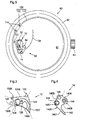
- FIGS. 7a, 7b and 7c show, in three sequences, the operation of a traditional ringing mechanism of a watch, and highlights its disadvantages.
- the spout 3, carried by the head 2 located at the front of the hammer 1, is slightly away from the stamp 100, while the tail 4, located at the rear of the hammer 1, is held between two elastic stops 7 and 8.
- the position of one of these elastic stops 7 is finely adjusted by means of an eccentric 9, which allows to finely adjust the distance of the spout 3 relative to the stamp 100 when the hammer 1 is in the rest position.
- the other stop 8 exerts a restoring force (arrow 90) to hold the tail 4 against the adjustable stop 7.
- the hammer 1 is released and rotates in the other direction about its axis 5.
- the elastic stop 8 brings the tail 4 towards the adjustable elastic stop 7 (arrow 90).
- the tail 4 hits the adjustable stop 7 (impact 88). Due to its elasticity, this adjustable stop 7 allows the head 2 of the hammer 1 to go beyond its rest position, and allows the spout 3 to hit the stamp 100 (impact 86).
- the adjustable elastic stop 7 then exerts a restoring force (arrows 92) on the shank 4 and tends to move the spout 3 away from the stamp 100.
- the hammer 1 is then brought back to the rest position ( figure 7a ), position in which the spout 3 is slightly spaced from the stamp 100. This stabilization of the hammer 1 lasts longer or shorter, depending on the elasticity of the two stops 7, 8 and the fineness of adjustment of the position of the stop adjustable 7.
- the skilled person may be tempted to reduce the stiffness of the elastic stops 7, 8. But then, the hammer 1 may not be brought back quickly enough to the rest position after its impact on the stamp 100, which may cause a rebound phenomenon. In addition, the rebound phenomenon can be accentuated if the position of the adjustable elastic stop 7 is not adjusted with sufficient precision.
- An object of the present invention is to provide a hammer for a clockwork mechanism, and a clockwork mechanism, including a striking mechanism equipped with such a hammer, which overcome the disadvantages mentioned above.
- the invention relates to a clockwork mechanism equipped with a hammer according to the first aspect.
- the invention relates to a striking mechanism for a timepiece, of the type comprising a fixed element able to vibrate when struck and a movable element able to hit said fixed element, in which the mobile element is a hammer according to the first aspect.
- the invention relates to a timepiece comprising a hammer according to the first aspect or a mechanism according to the second or third aspect.
- a timepiece is for example a watch, including a wristwatch, or an alarm clock, or a clock, or a clock.
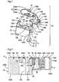
- a timepiece such as a watch 60 having a housing having a bottom 61 and a middle part 62, a winding device 63, and a striking mechanism 50.
- the striking mechanism 50 comprises a stamp 100 which presents itself in the form of a bent wire 110 extending around the perimeter of the middle part 62 and terminated by a heel 112 fixed to an element of the limp, such as for example to said middle part 62, by conventional fixing means such as 114.
- the striking mechanism 50 also includes a hammer 10. which has a spout 122 adapted to hit the thread 110 of the stamp 100 to vibrate.
- the hammer 10 comprises a first portion 12 and a second portion 14, which are hinged together by a hinge-type connection 70 cooperating with a return piece 16.
- the return piece 16 is rigidly attached to the first portion 12 and adapted to pivot with it relative to the second portion 14. It comprises an elastic member 162 which intervenes to oppose this pivoting.
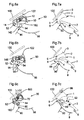
- the first portion 12 is a solid piece limited by two faces 1202, 1204 substantially parallel to each other and substantially parallel to the bottom 61 of the housing when the hammer 10 is installed in the timepiece 60, the face 1202 being an upper face and the face 1204 being a lower face.
- the upper faces 1202 and lower 1204 are connected by a lateral face 1205 defining a closed contour.
- the lateral face 1205 of the first portion 12 comprises, successively, a first substantially straight section 1206 intended to be positioned substantially parallel to the stamp 100 when the hammer 10 is installed in the housing of the timepiece 60, a second section 1207 arcuate and convex, a third section 1208 arcuate and concave, and a fourth section 1209 which will be described later.
- These sections 1206, 1207, 1208, 1209 are separated on the figure 3 by mixed lines.
- the first, second and third sections 1206, 1207 and 1208 define a shape substantially similar to that of the front of a monobloc hammer of the prior art (see Figures 7a, 7b, 7c ).
- the first section 1206 is provided with a spout 122 which is positioned opposite the stamp 100 when the hammer 10 is installed in the timepiece 60 (see FIG. figure 5 ), and which is similar to the spout 3 of a one-piece hammer of the prior art (see Figures 7a, 7b, 7c ).
- a ring 125 whose inner diameter is determined extends from the fourth section 1209 of the lateral face of the first part 12.
- the first portion 12 comprises a recess 124 made on the upper face 1202 and intended to receive the return piece 16.
- a threaded hole 126 In the bottom of this recess 124 are drilled a threaded hole 126 and a smooth hole 128.
- the bottom of the recess 124 is substantially planar
- the threaded hole 126 is a through hole
- the smooth hole 128 is a hole opening into another smooth hole 129 of larger diameter, which in turn opens on the lower face 1204.
- the second portion 14 is limited by two faces 1402, 1404 substantially parallel to each other and substantially parallel to the bottom 61 of the housing when the hammer 10 is installed in the timepiece 60, the face 1402 being an upper face and the face 1404 being a lower face.
- the upper faces 1402 and lower 1404 are connected by a lateral face 1405 defining a closed contour.
- the upper face 1402 of the second portion 14 extends substantially in the extension of the bottom plane of the recess 124 of the first portion 12.
- the distance between the upper faces 1402 and lower 1404 of the second portion 14 is less than the distance between the upper faces 1202 and lower 1204 of the first part 12. In particular, because of this difference in height between the two parts 12 and 14, it follows that the second part 14 is less massive and less heavy than the first part 12.
- the lateral face 1405 of the second portion 14 comprises, successively, a first section 1406, a second segment 1407 that is substantially rectilinear, a third segment 1408 having a rectilinear portion followed by a curved and concave portion, and a fourth section 1409 which will be described later.
- These sections 1406, 1407, 1408, 1409 are separated on the figure 4 by mixed lines.
- the first, second and third sections 1406, 1407 and 1408 define a shape substantially similar to that of the rear of a one-piece hammer of the prior art.
- the second section 1407 and the third section 1408 define a shank 142 of the second portion 14 of the hammer 10, similar to the shank 4 of a one-piece hammer of the prior art (see FIG. Figures 7a, 7b, 7c ).
- the second portion 14 comprises a first smooth through hole 145, intended to receive in rotation a fixed axis 52 of the striking mechanism 50 around which said second portion 14 of the hammer 10 can oscillate (see Figures 6a, 6b, 6c ).
- the second portion 14 includes a stop 144, intended to limit the displacement of a free end 1620 of an elastic member 162 of the workpiece recall 16 as will be described later with reference to Figures 6a, 6b, 6c .
- the abutment 144 is in the form of an annular bead disposed in the axial extension of the first through-hole 145.
- the second portion 14 comprises a drive means 148, for rotating the second portion 14 about the fixed axis 52 of the striking mechanism 50.
- this means drive 148 is in the form of an obviously adapted to receive a finger (not shown) adapted to cooperate with other drive means (not shown in the figures) of the striking mechanism 50 in a conventional manner.
- the second portion 14 has a second smooth through hole 146, which opens on one side on the upper face 1402 and on the other side on the lower face 1404 which is here closer to the face 1402.
- the second part 14 presents locally a reduced height (visible on the figure 2 ), which further accentuates the difference of inertia between the two parts 12, 14.
- the fourth portion 1209 of the lateral face 1205 of the first portion 12 and the fourth portion 1409 of the lateral face 1405 of the second portion 14 each have two adjacent opposite curvatures disposed between two substantially planar portions.
- These similar and almost complementary forms allow a displacement, by rolling, two parts 12, 14 relative to each other, this displacement being limited on both sides by said substantially planar portions.
- the return piece 16 will now be described with reference to the figure 1 . It comprises a body 164 and an elastic member 162 having a free end 1620.
- the body 164 is preferably rigid. It is intended to be rigidly fixed in the recess 124 of the first part 12. For this purpose, at least a portion of the recess 124 and at least a portion of the body 164 have complementary shapes.
- the body 164 is provided with a first smooth through hole 1642 and a second smooth through hole 1644.
- a clamping screw 18 is threaded through said first hole 1642 into the threaded hole 126 of the recess 124 to rigidly secure the body 164 of the return piece 16 to the first part 12.
- a stabilizing pin 19 passes through said second hole 1644 of the restoring piece 16 and is forcibly inserted into the smooth hole 128 of the recess 124, in order to prevent any relative movement between the body 164 of the return piece 16 and the first part 12.
- the elastic member 162 is preferably in the form of a flexible blade.
- the body 164 and the elastic member 162 are connected via a bendable and elastic coupling portion 168 which extends the elastic member 162 and positions it opposite the body 164, so that the elastic member 162 is able to move towards and move away elastically from the body 164.
- the hollow 124 comprises, in addition to a complementary portion of the body 164, a curved portion opening on the side face 1205, more precisely on the third section 1208, and for receiving said connecting portion 166.
- the connecting portion 166 is free to move in the curved portion of the recess 124, parallel to the plane thereof, to allow a reciprocating movement of the elastic member 162 relative to the body 164.
- the body 164 further comprises a third smooth through hole 76.
- This third hole 76 is disposed towards the free end 1640 of the body 164.
- the articulated assembly of the two parts 12, 14 implements a hinge pin 71 and an annular cylindrical piece 75 bearing office.
- the hinge pin 71 comprises a first rod 72 extending by a second rod 73 coaxial and larger diameter, which is in turn extended by a plate 74 of larger diameter.
- the hinge pin 71 is made integral with the first part 12 by forcible embedding of the second rod 73 in the ring 125 of the first part 12, the first rod 72 protruding from the ring 125 on the side of the upper face 1202, and the plate 74 abutting against the underside 1204.
- the annular cylindrical piece 75 has a determined height and outside diameter that allows it to be force-fitted into the second through hole 146 of the second portion 14. It has an inner hole 78 having a determined diameter, which is substantially identical to the diameter of the third through hole 76 of the return piece 16 and the diameter of the first rod 72 of the hinge pin 71. It constitutes a bearing which can be made of ruby.
- the hinge-type connection 70 comprises a hinge pin which is embodied by the first rod 72 of the articulation pivot 71 secured to the first portion 12.
- the elastic member 162 of the return piece 16 is positioned so that its free end 1620 is between the stop 144 and the free end of the body 164, and that it bears resiliently against said abutment 144.
- FIG. figure 5 is a stable configuration in which the two parts 12, 14 abut against each other.
- This abutment is achieved by abutting the flat portions of their fourth respective sections 1209, 1409 which are located on the side of their respective third sections 1208, 1408. Said respective third sections 1208, 1408 are then in contact with each other. other, while their respective first portions 1206, 1406 are spaced from each other.
- the two parts 12, 14 can be rotated relative to each other about the axis 72 of the hinge-type articulation 70, thanks to the complementary shapes of their fourth respective sections 1209, 1409.
- these complementary shapes can roll on one another.
- the hammer 10 is then brought from its first configuration into a second configuration, which, in the extreme, is a configuration in which the two parts 12, 14 abut against each other.
- the latter abutment is achieved by abutting the flat portions of their fourth respective sections 1209, 1409 which are located on the side of their respective first sections 1206, 1406.
- Said first respective sections 1206, 1406 are then in contact with each other. the other, while their respective third sections 1208, 1408 are spaced apart from each other.
- this second configuration is not a stable configuration for the hammer 10. Indeed, as soon as the external stress ceases, the elastic member 162 of the part 16, which is pressed against the abutment 144, relaxes and returns the hammer 10 in its first configuration, which is a stable configuration.
- this Extra run of the first part 12 is between 3 degrees and 40 degrees. More preferably, it is between 10 degrees and 25 degrees. In particular, it is substantially equal to 20 degrees.
- the figure 6a represents the striking mechanism 50 with the hammer 10 in the rest position.
- the hammer 10 is in its first, stable configuration, which has been described above, in which it has substantially the same shape as a hammer 1 monoblock of the prior art ( Figures 7a, 7b, 7c ).
- the figure 6b represents the striking mechanism 50 during the arming phase of the hammer 10, which consists in driving in rotation (arrow 96) its second part 14 about an axis 52, which is a fixed axis relative to the striking bridge, and which is installed in the through hole 145 of the second portion 14.
- This rotational movement of the second portion 14 is effected by means of a drive means 148 of the second portion 14, which cooperates with another means of drive (not shown) of the striking mechanism 50, such as for example a training lift.
- the tail 142 of the second portion 14 moves away from the fixed stop 54, and opposes the action of return of the elastic stop 56 (arrows 90).
- the rotational movement of the second portion 14 has no influence on the configuration of the hammer 10, since this displacement does not oppose the return action of the elastic member 162 of the return piece 16.
- the hammer 10 remains in its first configuration, stable, and the first portion 12 is also rotated.
- the hammer 10 behaves like a hammer 1 monoblock of the prior art, and the beak 122 away from the stamp 100.
- the Figure 6c represents the striking mechanism 50 during the striking phase of the hammer 10 on the stamp 100, which is caused by the end of the rotation of the second part 14.
- This second part 14 is released and turns in the other direction around the fixed axis 52, under the action of the elastic stop 56.
- the action of return of the elastic stop 56 brings the tail 142 against the fixed stop 54, which results in a first shock (Impact 80) in which part of the kinetic energy stored in the second part 14 during the arming phase is released. But most of this kinetic energy is immediately used in an additional movement of the first portion 12, which is then rotated relative to the second portion 14 about the hinge axis 72 of the hammer 10, against the action of the elastic member 162 of the return piece 16.
- the relative position of the two axes of rotation 52, 72 is chosen such that the speed of the first part 12 increases between its first trajectory (overall rotation of the two parts 12, 14 about the axis 52) and its additional trajectory (rotation of the first part 12 compared to the second part 14). This speed is also increased by the difference in inertia between the first part 12 and the second part 14, the first part 12 being constructed, preferably, heavier than the second part 14.
- the beak 122 of the first part 14 then comes into being hitting the stamp 100 with a significant kinetic energy stored by the first part 12, which results in a second shock (impact 800) greater than the first shock (impact 80).
- the first part 12 is brought into reverse rotation around the axis of rotation 72, under the action of return of the elastic member 182 of the piece of 16. This return is made quickly and without rebound, because the first portion 12 is free to rotate relative to the second portion 14, and the fact that the spring constituted by the elastic member 162 is weak.
- the hammer 10 is brought back and maintained in its first configuration, stable.
- the shank 142 is retained against the fixed stop 54 by the action of return of the elastic stop 56.
- the hammer 10 and the striking mechanism 50 according to the invention have certain advantages over those of the prior art.
- the hammer 10 according to the invention is a hammer in two parts 12, 14 articulated, while the hammer 1 according to the prior art is a one-piece hammer.
- This characteristic is not significant when the hammer 10 is in the rest position or during the arming phase, because it behaves like a one-piece hammer.
- most of the kinetic energy stored in the hammer during the arming phase is restored in the impact of the beak 122 against the stamp 100 rather than in the shock of the tail 142 with the fixed stop 54.
- the sound obtained is stronger with the hammer 10 according to the invention with the hammer 1 of the prior art.
- the position of this fixed stop 54 is determined once and for all to adjust the position of the beak 122 with respect to the stamp 100 in the rest position of the hammer 10 ( figure 6a ).
- This position is not critical. Indeed, the distance between the nozzle 122 and the stamp 100 does not depend only on the position of this fixed stop 54, but also depends on the additional stroke of the first part 12 with respect to the second part 14.
- the distance between the spout 122 and the stamp 100 in the rest position of the hammer 10 ( figure 6a ) of the striking mechanism 50 of the invention can be chosen slightly larger than the distance between the spout 3 and the stamp 100 in the rest position of the hammer 1 ( figure 7a ) of the ringing mechanism of the prior art.
- a clock mechanism according to the invention and in particular a striking mechanism 50, which comprises a hammer 10 in two parts 12, 14 hinged together and a fixed stop 54 proves to be more advantageous than a timepiece mechanism.
- the prior art which comprises a hammer 1 monobloc and an adjustable elastic stop 7.
- the abutment 144 placed on the upper face 1402 of the second portion 14, and serving to limit the displacement of the free end 1620 of the elastic member 162 of the return piece 16, may not be in line with the bearing 146 .
- the holes 126, 128 made in the bottom of the recess 124 could be blind holes instead of being through holes.
- the invention would apply with a hammer 10 having a general shape (in stable configuration) different from that of the illustrated embodiment.
- the complementary shapes of the fourth respective sections 1209, 1409 of the first portion 12 and the second portion 14 could be different from the forms described.
- the fourth sections 1209, 1409 could be in the form of grooves whose respective edges would alternately abut to limit the relative displacement of the two parts 12, 14, and therefore limit the additional stroke of the first part 12.
Abstract
Description
La présente invention se rapporte au domaine des pièces d'horlogerie et vise plus particulièrement un marteau pour un mécanisme d'horlogerie, tel qu'un mécanisme de sonnerie. Elle vise encore un mécanisme d'horlogerie, notamment un mécanisme de sonnerie, équipé d'un tel marteau. Elle vise enfin une pièce d'horlogerie comportant un tel marteau ou un tel mécanisme.The present invention relates to the field of timepieces and more particularly to a hammer for a clockwork mechanism, such as a striking mechanism. It also aims a clockwork mechanism, including a striking mechanism, equipped with such a hammer. It finally aims a timepiece including such a hammer or such a mechanism.
On connaît déjà des mécanismes d'horlogerie qui utilisent un marteau comme les mécanismes de remise à zéro dans les chronographes et les mécanismes de sonneries. En général, le marteau est une pièce métallique massive traversée d'un axe. Notamment, dans les sonneries, le marteau frappe un élément fixe susceptible d'être mis en vibration et, lorsque l'élément fixe est frappé, il se met à vibrer et à transmettre sa vibration aux éléments rayonnants de la pièce d'horlogerie. Dans le cas d'une horloge, l'élément fixe est typiquement une cloche, et dans le cas d'une montre l'élément fixe est typiquement un timbre. Le timbre est généralement un fil métallique cintré qui s'étend le long du pourtour de la carrure de la montre, et qui est fixé à un élément de son boîtier. Le marteau oscille autour de cet axe de manière à s'écarter du timbre ou à s'en approcher pour le frapper et le mettre en vibration.Watchmaking mechanisms that use a hammer are already known, such as reset mechanisms in chronographs and ringer mechanisms. In general, the hammer is a massive metal piece crossed by an axis. In particular, in ringtones, the hammer strikes a fixed element capable of being vibrated and, when the fixed element is struck, it begins to vibrate and transmit its vibration to the radiating elements of the timepiece. In the case of a clock, the fixed element is typically a bell, and in the case of a watch the fixed element is typically a stamp. The stamp is generally a bent wire which extends along the periphery of the middle part of the watch, and which is attached to an element of its case. The hammer oscillates around this axis so as to deviate from the timbre or to approach it to hit it and put it in vibration.
Deux qualités principales sont recherchées pour un mécanisme de sonnerie. Il faut que l'impact soit franc, d'une durée suffisante pour l'excitation des composantes graves de la note et assez brève pour la netteté de l'attaque.Two main qualities are sought for a striking mechanism. It is necessary that the impact is frank, of a sufficient duration for the excitation of the serious components of the note and rather brief for the sharpness of the attack.
Dans le cas des montres à complication de sonnerie, la qualité et la robustesse du son naissent des caractéristiques du choc, qui sont fixées par la conception et le réglage du mécanisme de frappe. En particulier, il faut que le marteau s'écarte de l'élément fixe après l'avoir frappé, afin que celui-ci puisse vibrer librement, en évitant tout phénomène de rebond, c'est-à-dire le fait que le marteau n'entre en contact avec l'élément fixe une deuxième fois, voire une troisième fois, après l'avoir frappé une première fois.In the case of bell complication watches, sound quality and robustness arise from the shock characteristics, which are determined by the design and adjustment of the striking mechanism. In particular, it is necessary that the hammer deviates from the fixed element after having struck it, so that it can vibrate freely, avoiding any rebound phenomenon, that is to say the fact that the hammer does not come into contact with the fixed element a second time, even a third time, after hitting it a first time.
Les
En position de repos du marteau 1 (
Lors de la phase d'armage du marteau 1 (
Lors de la phase de frappe du marteau 1 sur le timbre 100 (
Le marteau 1 est alors ramené en position de repos (
Les inconvénients d'un agencement tel que celui qui vient d'être décrit apparaissent clairement.The disadvantages of an arrangement such as that which has just been described appear clearly.
Du fait que la queue 4 du marteau 1 vient frapper la butée réglable 7 (impact 88) avant que le bec 3 ne vienne frapper le timbre 100 (impact 86), la plus grande partie de l'énergie cinétique emmagasinée lors de la phase d'armage est dissipée dans le choc de la queue 4 avec la butée élastique réglable 7. L'énergie cinétique disponible au moment de l'impact du bec 3 de la tête 2 avec le timbre 100 est moindre. Ce phénomène est illustré à la
Pour éviter ce phénomène, l'homme du métier peut être tenté de diminuer la raideur des butées élastique 7, 8. Mais alors, le marteau 1 risque de ne pas être ramené suffisamment vite en position de repos après son impact sur le timbre 100, ce qui risque de provoquer un phénomène de rebond. En outre, le phénomène de rebond peut être accentué si la position de la butée élastique réglable 7 n'est pas réglée avec suffisamment de précision.To avoid this phenomenon, the skilled person may be tempted to reduce the stiffness of the
Avec le mécanisme de sonnerie de la technique antérieure, il s'avère donc nécessaire de déterminer très finement la raideur des deux butées élastiques 7, 8, ainsi que la position de la butée élastique réglable 7.With the striking mechanism of the prior art, it is therefore necessary to determine very finely the stiffness of the two
Un but de la présente invention est de proposer un marteau pour un mécanisme d'horlogerie, ainsi qu'un mécanisme d'horlogerie, notamment un mécanisme de sonnerie équipé d'un tel marteau, qui surmontent les inconvénients évoqués ci-dessus.An object of the present invention is to provide a hammer for a clockwork mechanism, and a clockwork mechanism, including a striking mechanism equipped with such a hammer, which overcome the disadvantages mentioned above.
Selon un premier aspect, l'invention se rapporte à un marteau pour un mécanisme d'une pièce d'horlogerie, comportant :
- une première partie et une deuxième partie qui sont articulées entre elles, et
- un organe élastique fixé sur l'une desdites deux parties,
- a first part and a second part which are articulated with each other, and
- an elastic member fixed on one of said two parts,
Des formes d'exécution particulières du marteau selon le premier aspect de l'invention sont définies dans les revendications dépendantes annexées 2 à 14.Particular embodiments of the hammer according to the first aspect of the invention are defined in the appended
Selon un deuxième aspect, l'invention se rapporte à un mécanisme d'horlogerie équipé d'un marteau selon le premier aspect.According to a second aspect, the invention relates to a clockwork mechanism equipped with a hammer according to the first aspect.
Selon un troisième aspect, l'invention se rapporte à un mécanisme de sonnerie pour une pièce d'horlogerie, du type comportant un élément fixe apte à vibrer lorsqu'il est frappé et un élément mobile apte à frapper ledit élément fixe, dans lequel l'élément mobile est un marteau selon le premier aspect.According to a third aspect, the invention relates to a striking mechanism for a timepiece, of the type comprising a fixed element able to vibrate when struck and a movable element able to hit said fixed element, in which the mobile element is a hammer according to the first aspect.
Selon un quatrième aspect, l'invention se rapporte à une pièce d'horlogerie comportant un marteau selon le premier aspect ou un mécanisme selon le deuxième ou le troisième aspect. Une telle pièce d'horlogerie est par exemple une montre, notamment une montre-bracelet, ou un réveil, ou une pendule, ou une horloge.According to a fourth aspect, the invention relates to a timepiece comprising a hammer according to the first aspect or a mechanism according to the second or third aspect. Such a timepiece is for example a watch, including a wristwatch, or an alarm clock, or a clock, or a clock.
L'invention sera mieux comprise à la lecture de la description détaillée qui va suivre, d'un mode de réalisation particulier de l'invention, fourni à titre illustratif et non limitatif, en référence aux dessins annexés, dans lesquels :
- la
figure 1 représente, en perspective supérieure et en éclaté, un marteau selon l'invention ; - la
figure 2 représente, en coupe longitudinale, le marteau de lafigure 1 ; - la
figure 3 est une vue de dessus de la première partie du marteau ; - la
figure 4 est une vue de dessus de la deuxième partie du marteau ; - la
figure 5 représente, en vue de dessus et de manière schématique, l'intérieur d'une montre comportant un marteau selon l'invention ; - les
figures 6a, 6b, 6c représentent, en vue de dessus et de manière schématique, trois séquences du fonctionnement d'un mécanisme de sonnerie selon l'invention ; et - les
figures 7a, 7b, 7c , déjà décrites, sont analogues à lafigure 6 pour un mécanisme de sonnerie de la technique antérieure.
- the
figure 1 represents, in upper perspective and exploded, a hammer according to the invention; - the
figure 2 represents, in longitudinal section, the hammer of thefigure 1 ; - the
figure 3 is a top view of the first part of the hammer; - the
figure 4 is a top view of the second part of the hammer; - the
figure 5 represents, in plan view and schematically, the inside of a watch comprising a hammer according to the invention; - the
Figures 6a, 6b, 6c represent, in plan view and schematically, three sequences of the operation of a striking mechanism according to the invention; and - the
Figures 7a, 7b, 7c , already described, are analogous to thefigure 6 for a ringing mechanism of the prior art.
En se référant tout d'abord à la
En se référant maintenant aux
La première partie 12 est une pièce massive limitée par deux faces 1202, 1204 sensiblement parallèles entre elles et sensiblement parallèles au fond 61 du boîtier lorsque le marteau 10 est installé dans la pièce d'horlogerie 60, la face 1202 étant une face supérieure et la face 1204 étant une face inférieure. Les faces supérieure 1202 et inférieure 1204 sont reliées par une face latérale 1205 définissant un contour fermé.The
Comme illustré sur la
Les premier, deuxième et troisième tronçons 1206, 1207 et 1208 définissent une forme sensiblement analogue à celle de l'avant d'un marteau monobloc de la technique antérieure (voir
Comme illustré aux
Comme le montrent les
La deuxième partie 14 est limitée par deux faces 1402, 1404 sensiblement parallèles entre elles et sensiblement parallèles au fond 61 du boîtier lorsque le marteau 10 est installé dans la pièce d'horlogerie 60, la face 1402 étant une face supérieure et la face 1404 étant une face inférieure. Les faces supérieure 1402 et inférieure 1404 sont reliées par une face latérale 1405 définissant un contour fermé.The
Quand les deux parties 12, 14 sont assemblées pour former le marteau 10 (voir
Comme illustré sur la
Les premier, deuxième et troisième tronçons 1406, 1407 et 1408 définissent une forme sensiblement analogue à celle de l'arrière d'un marteau monobloc de la technique antérieure. En particulier, le deuxième tronçon 1407 et le troisième tronçon 1408 définissent une queue 142 de la deuxième partie 14 du marteau 10, analogue à la queue 4 d'un marteau monobloc de la technique antérieure (voir
Vers la jonction entre les premier et deuxième tronçons 1406, 1407, la deuxième partie 14 comporte un premier trou traversant lisse 145, destiné à recevoir en rotation un axe fixe 52 du mécanisme de sonnerie 50 autour duquel ladite deuxième partie 14 du marteau 10 peut osciller (voir
Toujours vers la jonction entre les premier et deuxième tronçons 1406, 1407, et sur sa face supérieure 1402, la deuxième partie 14 comporte une butée 144, destinée à limiter le déplacement d'une extrémité libre 1620 d'un organe élastique 162 de la pièce de rappel 16 comme il sera décrit plus loin en référence aux
Au niveau du premier tronçon 1406, la deuxième partie 14 comporte un moyen d'entraînement 148, pour entraîner en rotation la deuxième partie 14 autour de l'axe fixe 52 du mécanisme de sonnerie 50. Selon l'exemple illustré aux figures, ce moyen d'entraînement 148 se présente sous la forme d'un évidemment apte à recevoir un doigt (non représenté) apte à coopérer avec d'autres moyens d'entraînement (non représentés aux figures) du mécanisme de sonnerie 50 de manière conventionnelle.At the
Au niveau du quatrième tronçon 1409, la deuxième partie 14 comporte un deuxième trou traversant lisse 146, qui débouche d'un côté sur la face supérieure 1402 et de l'autre côté sur la face inférieure 1404 qui se trouve ici plus proche de la face supérieure 1402. La deuxième partie 14 présente localement une hauteur réduite (visible sur la
Comme représenté sur les
La pièce de rappel 16 va maintenant être décrite en référence à la
Le corps 164 est de préférence rigide. Il est destiné à être rigidement fixé dans la creusure 124 de la première partie 12. A cet effet, au moins une portion de la creusure 124 et au moins une portion du corps 164 présentent des formes complémentaires. Le corps 164 est doté d'un premier trou traversant lisse 1642 et d'un deuxième trou traversant lisse 1644. Une vis de serrage 18 est vissée à travers ledit premier trou 1642 dans le trou fileté 126 de la creusure 124, pour fixer rigidement le corps 164 de la pièce de rappel 16 à la première partie 12. Une goupille de stabilisation 19 traverse ledit deuxième trou 1644 de la pièce de rappel 16 et est enchâssée à force dans le trou lisse 128 de la creusure 124, afin d'empêcher tout mouvement relatif entre le corps 164 de la pièce de rappel 16 et la première partie 12.The
L'organe élastique 162 se présente de préférence sous la forme d'une lame flexible. Le corps 164 et l'organe élastique 162 sont raccordés par l'intermédiaire d'une portion de raccord 168 courbée et élastique qui prolonge l'organe élastique 162 et le positionne en regard du corps 164, de telle sorte que l'organe élastique 162 est apte à se rapprocher et à s'écarter élastiquement du corps 164. Comme illustré sur la
Sur une portion qui n'est pas destinée à être reçue par la creusure 124, le corps 164 comporte, en outre, un troisième trou traversant lisse 76. Ce troisième trou 76 est disposé vers l'extrémité libre 1640 du corps 164. Lorsque la pièce de rappel 16 est fixée sur la première partie 12, le troisième trou 76 du corps de la pièce de rappel 16 et l'anneau 125 de la première partie 12 sont alignés.On a portion that is not intended to be received by the
On va maintenant décrire plus en détail l'assemblage articulé des deux parties 12, 14 du marteau 10. Cet assemblage articulé est réalisé au niveau des quatrièmes tronçons respectifs 1209, 1409 des faces latérales respectives 1205, 1405 des deux parties 12, 14 par une liaison de type charnière 70.The articulated assembly of the two
Selon le mode de réalisation illustré aux figures, l'assemblage articulé des deux parties 12, 14 met en oeuvre un pivot d'articulation 71 et une pièce cylindrique annulaire 75 faisant office de palier.According to the embodiment illustrated in the figures, the articulated assembly of the two
Le pivot d'articulation 71 comporte une première tige 72 se prolongeant par une deuxième tige 73 coaxiale et de plus grand diamètre, laquelle se prolonge à son tour par une plaque 74 de plus grand diamètre. Le pivot d'articulation 71 est rendu solidaire de la première partie 12 par enchâssement à force de la deuxième tige 73 dans l'anneau 125 de la première partie 12, la première tige 72 dépassant de l'anneau 125 du côté de la face supérieure 1202, et la plaque 74 venant buter contre la face inférieure 1204.The
La pièce cylindrique annulaire 75 présente une hauteur et un diamètre extérieur déterminés qui lui permettent d'être enchâssée à force dans le deuxième trou traversant 146 de la deuxième partie 14. Elle présente un trou intérieur 78 ayant un diamètre déterminé, qui est sensiblement identique au diamètre du troisième trou traversant 76 de la pièce de rappel 16 et au diamètre de la première tige 72 du pivot d'articulation 71. Elle constitue un palier qui peut être réalisé en rubis.The annular
La liaison de type charnière 70 comporte un axe d'articulation qui est matérialisé par la première tige 72 du pivot d'articulation 71 rendu solidaire de la première partie 12.The hinge-
Lorsque les deux parties 12, 14 sont assemblées au moyen de l'articulation de type charnière 70 pour former le marteau 10, l'organe élastique 162 de la pièce de rappel 16 est positionné de telle façon que son extrémité libre 1620 se trouve entre la butée 144 et l'extrémité libre du corps 164, et qu'elle s'appuie élastiquement contre ladite butée 144.When the two
Lorsque le marteau 10 n'est soumis à aucune sollicitation extérieure, l'organe élastique 162 et son extrémité libre 1620 en appui contre la butée 144 ont pour effet de maintenir le marteau 10 dans une première configuration, illustrée à la
Sous l'action d'une sollicitation extérieure, les deux parties 12, 14 peuvent être amenées à tourner l'une par rapport à l'autre autour de l'axe 72 de l'articulation de type charnière 70, grâce aux formes complémentaires de leurs quatrièmes tronçons respectifs 1209, 1409. Sur l'exemple illustré, ces formes complémentaires peuvent rouler l'une sur l'autre. Le marteau 10 est alors amené de sa première configuration dans une deuxième configuration, qui, à l'extrême, est une configuration dans laquelle les deux parties 12, 14 sont en butée l'une contre l'autre. Cette dernière butée est réalisée par la mise en butée des portions planes de leurs quatrièmes tronçons respectifs 1209, 1409 qui sont situés du côté de leurs premiers tronçons respectifs 1206, 1406. Lesdits premiers tronçons respectifs 1206, 1406 sont alors en contact l'un avec l'autre, tandis que leurs troisièmes tronçons respectifs 1208, 1408 sont écartés l'un de l'autre. Mais cette deuxième configuration n'est pas une configuration stable pour le marteau 10. En effet, dès que la sollicitation extérieure cesse, l'organe élastique 162 de la pièce de rappel 16, qui est appuyé contre la butée 144, se détend et ramène le marteau 10 dans sa première configuration, qui est une configuration stable.Under the action of an external stress, the two
Le déplacement relatif, par roulement, des quatrièmes tronçons respectifs 1209, 1409 des deux parties 12, 14 est limité par des portions planes situées de part et d'autre de leurs courbures opposées et adjacentes. Par conséquent, le déplacement relatif des deux parties 12, 14 est également limité. Par suite, la course supplémentaire de la première partie 12 au-delà de la course de la deuxième partie 14 est également limitée, entre la première configuration, stable, du marteau 10 et la deuxième configuration extrême du marteau 10. De manière préférée, cette course supplémentaire de la première partie 12 est comprise entre 3 degrés et 40 degrés. De manière plus préférée, elle est comprise entre 10 degrés et 25 degrés. En particulier, elle est sensiblement égale à 20 degrés.Relative displacement, rolling, the fourth
On va maintenant décrire le fonctionnement d'un mécanisme de sonnerie 50 équipé du marteau 10 selon l'invention, en référence aux
La
Dans cette position de repos du marteau 10, son bec 122 se trouve à une distance relativement faible du timbre 100, cette position du bec 122, et donc du marteau 10, étant déterminée par le fait que la queue 142 du marteau 10 est en appui contre une butée fixe 54 du mécanisme de sonnerie 50, et maintenue contre cette butée fixe 54 (flèche 90) par une butée élastique 56 du mécanisme de sonnerie 50. Ladite butée fixe 54 peut prendre la forme d'une goupille enchâssée dans le pont de sonnerie (non représenté) de la pièce d'horlogerie 60, tandis que ladite butée élastique 56 peut être analogue à la butée élastique 8 de la technique antérieure (
La
Lors de cette phase d'armage, la queue 142 de la deuxième partie 14 s'éloigne de la butée fixe 54, et s'oppose à l'action de rappel de la butée élastique 56 (flèches 90). Le déplacement en rotation de la deuxième partie 14 n'a pas d'influence sur la configuration du marteau 10, car ce déplacement ne s'oppose pas à l'action de rappel de l'organe élastique 162 de la pièce de rappel 16. Le marteau 10 reste dans sa première configuration, stable, et la première partie 12 est également entraînée en rotation. Au cours de la phase d'armage, le marteau 10 se comporte comme un marteau 1 monobloc de la technique antérieure, et le bec 122 s'éloigne du timbre 100.During this arming phase, the
La
Le marteau 10 et le mécanisme de sonnerie 50 selon l'invention présentent des avantages certains par rapport à ceux de la technique antérieure.The
Le marteau 10 selon l'invention est un marteau en deux parties 12, 14 articulées, alors que le marteau 1 selon la technique antérieure est un marteau monobloc. Cette caractéristique n'est pas significative lorsque le marteau 10 est en position de repos ou lors de la phase d'armage, car il se comporte comme un marteau monobloc. En revanche, lors de la phase de frappe, la plus grande partie de l'énergie cinétique emmagasinée dans le marteau lors de la phase d'armage est restituée dans le choc du bec 122 contre le timbre 100 plutôt que dans le choc de la queue 142 avec la butée fixe 54. Le son obtenu est plus fort avec le marteau 10 selon l'invention qu'avec le marteau 1 de la technique antérieure.The
De plus, avec l'agencement de la technique antérieure, il est nécessaire que la queue 4 soit ramenée contre une butée élastique 7 qui autorise le marteau à aller au-delà de sa position de repos, afin que le bec 3 percute le timbre 100. En revanche, avec le marteau 10 selon l'invention, du fait que le déplacement supplémentaire de la première partie 12, et donc du bec 122, soit réalisé grâce à la présence de l'articulation de type charnière 70, une butée fixe 54 remplace avantageusement la butée élastique 7 de la technique antérieure.In addition, with the arrangement of the prior art, it is necessary that the tail 4 is brought against an
La position de cette butée fixe 54 est déterminée une fois pour toutes pour régler la position du bec 122 par rapport au timbre 100 dans la position de repos du marteau 10 (
Enfin, avec l'agencement de la technique antérieure, il est nécessaire de ramener le marteau 1 monobloc dans sa position de repos après le choc du bec 3 sur le timbre 100, ce retour étant à l'origine d'un phénomène de rebond. Au contraire, avec l'agencement selon l'invention, il suffit de ramener le marteau 10 dans sa configuration stable, par une rotation retour de la première partie 12 par rapport à la deuxième partie 14, cette deuxième partie 14 étant déjà maintenue en bonne position contre la butée fixe 54 sous l'action de rappel de la butée élastique 56. Cela a pour avantage de supprimer tout phénomène de rebond.Finally, with the arrangement of the prior art, it is necessary to bring the
Un mécanisme d'horlogerie selon l'invention, et notamment un mécanisme de sonnerie 50, qui comporte un marteau 10 en deux parties 12, 14 articulées entre elles et une butée fixe 54 s'avère plus avantageux qu'un mécanisme d'horlogerie de la technique antérieure, qui comporte un marteau 1 monobloc et une butée élastique réglable 7.A clock mechanism according to the invention, and in particular a
Bien entendu, l'invention n'est pas limitée au mode de réalisation qui a été illustré aux figures et couvre des variantes de réalisation à la portée de l'homme du métier.Of course, the invention is not limited to the embodiment that has been illustrated in the figures and covers variants within the scope of those skilled in the art.
La butée 144 placée sur la face supérieure 1402 de la deuxième partie 14, et servant à limiter le déplacement de l'extrémité libre 1620 de l'organe élastique 162 de la pièce de rappel 16, pourrait ne pas être dans le prolongement du palier 146.The
Les trous 126, 128 réalisés dans le fond de la creusure 124 pourraient être des trous borgnes au lieu d'être des trous traversants.The
L'invention s'appliquerait avec un marteau 10 ayant une forme générale (en configuration stable) différente de celle du mode de réalisation illustré.The invention would apply with a
En particulier, les formes complémentaires des quatrièmes tronçons respectifs 1209, 1409 de la première partie 12 et de la deuxième partie 14 pourraient être différentes des formes décrites. Pourraient convenir toutes formes complémentaires autorisant un déplacement relatif des deux parties 12, 14, ce déplacement relatif étant limité de part et d'autre par des portions formant butées. Par exemple, les quatrièmes tronçons 1209, 1409 pourraient se présenter sous forme de gorges dont les bords respectifs viendraient alternativement en butée pour limiter le déplacement relatif des deux parties 12, 14, et par suite limiter la course supplémentaire de la première partie 12.In particular, the complementary shapes of the fourth
Claims (18)
caractérisé par le fait qu'il comporte :
characterized by the fact that it comprises:
Applications Claiming Priority (1)
| Application Number | Priority Date | Filing Date | Title |
|---|---|---|---|
| CH15742007 | 2007-10-10 |
Publications (4)
| Publication Number | Publication Date |
|---|---|
| EP2048548A2 true EP2048548A2 (en) | 2009-04-15 |
| EP2048548A3 EP2048548A3 (en) | 2016-11-30 |
| EP2048548B1 EP2048548B1 (en) | 2021-08-18 |
| EP2048548B8 EP2048548B8 (en) | 2022-02-16 |
Family
ID=39767028
Family Applications (1)
| Application Number | Title | Priority Date | Filing Date |
|---|---|---|---|
| EP08016192.0A Active EP2048548B8 (en) | 2007-10-10 | 2008-09-15 | Striking mechanism |
Country Status (2)
| Country | Link |
|---|---|
| EP (1) | EP2048548B8 (en) |
| CN (1) | CN101441435B (en) |
Cited By (9)
| Publication number | Priority date | Publication date | Assignee | Title |
|---|---|---|---|---|
| EP2339412A2 (en) | 2009-12-24 | 2011-06-29 | Montres Breguet SA | Chiming mechanism of a watch |
| EP2362279A1 (en) | 2010-02-26 | 2011-08-31 | Montres Breguet SA | Chiming mechanism of a watch with active buffer counter spring |
| EP2463731A1 (en) * | 2010-12-10 | 2012-06-13 | Montres Breguet SA | Chiming mechanism of a watch |
| CH704392A1 (en) * | 2011-01-28 | 2012-07-31 | Montres Breguet Sa | striking mechanism of a hammer lock watch. |
| EP2767875A2 (en) | 2013-02-15 | 2014-08-20 | Richemont International S.A. | Striking mechanism and timepiece provided with said striking mechanism |
| EP3070540A1 (en) * | 2015-03-18 | 2016-09-21 | Glashütter Uhrenbetrieb GmbH | Hammer with resilient adjustable stop |
| JP2017067774A (en) * | 2015-09-28 | 2017-04-06 | ランゲ ウーレン ゲーエムベーハー | Hammer mechanism |
| EP2660662A3 (en) * | 2012-05-02 | 2018-01-17 | Patek Philippe SA Genève | Alarm mechanism |
| EP3543801A1 (en) * | 2018-03-21 | 2019-09-25 | Montres Breguet S.A. | Timepiece chiming mechanism |
Families Citing this family (4)
| Publication number | Priority date | Publication date | Assignee | Title |
|---|---|---|---|---|
| EP2362278B1 (en) * | 2010-02-26 | 2016-10-12 | Montres Breguet SA | Hammer for a stricking mechanism of a watch |
| JP5955004B2 (en) * | 2011-02-07 | 2016-07-20 | モントル チュードル ソシエテ アノニム | Watch movement parts |
| EP3663869B1 (en) | 2018-12-06 | 2021-06-16 | Montres Breguet S.A. | Timepiece chiming mechanism with suspended hammer |
| CN111897199B (en) * | 2020-08-28 | 2021-05-04 | 芜湖市创源新材料有限公司 | Electric drive awakens alarm clock up |
Family Cites Families (11)
| Publication number | Priority date | Publication date | Assignee | Title |
|---|---|---|---|---|
| US641478A (en) * | 1899-07-29 | 1900-01-16 | Enrique Torres | Repeating watch. |
| GB1110717A (en) * | 1964-10-09 | 1968-04-24 | D Horlogerie Chs Tissotet Fils | Alarm-bell mechanism for an alarm clock |
| DE4012026A1 (en) * | 1990-04-13 | 1991-10-17 | Int Watch Co Iwc | ANCHOR DEVICE |
| DE4012059A1 (en) * | 1990-04-13 | 1991-10-17 | Int Watch Co Iwc | REPEATING WATCH |
| CN2389381Y (en) * | 1999-09-14 | 2000-07-26 | 应东义 | Beater for time-piece |
| CH697380B1 (en) * | 2004-03-09 | 2008-09-15 | Franck Muller Watchland Sa | Timepiece repeatedly to minute. |
| EP1708050B1 (en) * | 2005-03-31 | 2008-05-14 | Zenith International SA | Timepiece with a minute-repeater mechanism |
| ATE512390T1 (en) * | 2005-06-27 | 2011-06-15 | Montres Breguet Sa | WATCH HAVING AN ACTUATING DEVICE OF A STRIKE MECHANISM WITH AN ELASTIC GEAR ELEMENT |
| JP4830667B2 (en) * | 2005-10-06 | 2011-12-07 | セイコーエプソン株式会社 | Speed governor and power generator and equipment using the same |
| EP1798610B1 (en) * | 2005-12-14 | 2008-10-22 | Montres Breguet S.A. | Timepiece including a single-pawl striking mechanism |
| EP1798611B1 (en) * | 2005-12-14 | 2008-05-07 | Montres Breguet S.A. | Timepiece including a striking mechanism with instant triggering |
-
2008
- 2008-09-15 EP EP08016192.0A patent/EP2048548B8/en active Active
- 2008-10-10 CN CN2008101692396A patent/CN101441435B/en active Active
Non-Patent Citations (1)
| Title |
|---|
| None * |
Cited By (20)
| Publication number | Priority date | Publication date | Assignee | Title |
|---|---|---|---|---|
| EP2339412A3 (en) * | 2009-12-24 | 2016-08-03 | Montres Breguet SA | Chiming mechanism of a watch |
| US8514669B2 (en) | 2009-12-24 | 2013-08-20 | Montres Breguet Sa | Strike mechanism for a watch |
| EP2339412A2 (en) | 2009-12-24 | 2011-06-29 | Montres Breguet SA | Chiming mechanism of a watch |
| EP2362279A1 (en) | 2010-02-26 | 2011-08-31 | Montres Breguet SA | Chiming mechanism of a watch with active buffer counter spring |
| US20110211427A1 (en) * | 2010-02-26 | 2011-09-01 | Montes Breguet S.A. | Striking mechanism for a watch with an active damper counter-spring |
| JP2011180140A (en) * | 2010-02-26 | 2011-09-15 | Montres Breguet Sa | Striking mechanism for watch with active damper counter-spring |
| US8547803B2 (en) | 2010-02-26 | 2013-10-01 | Montres Breguet S.A. | Striking mechanism for a watch with an active damper counter-spring |
| EP2463731A1 (en) * | 2010-12-10 | 2012-06-13 | Montres Breguet SA | Chiming mechanism of a watch |
| US8537642B2 (en) | 2010-12-10 | 2013-09-17 | Montres Breuguet SA | Watch striking mechanism |
| CH704392A1 (en) * | 2011-01-28 | 2012-07-31 | Montres Breguet Sa | striking mechanism of a hammer lock watch. |
| US8514670B2 (en) | 2011-01-28 | 2013-08-20 | Montres Breguet Sa | Striking mechanism for a watch with a hammer locking device |
| EP2660662A3 (en) * | 2012-05-02 | 2018-01-17 | Patek Philippe SA Genève | Alarm mechanism |
| EP2767875A2 (en) | 2013-02-15 | 2014-08-20 | Richemont International S.A. | Striking mechanism and timepiece provided with said striking mechanism |
| EP3070540A1 (en) * | 2015-03-18 | 2016-09-21 | Glashütter Uhrenbetrieb GmbH | Hammer with resilient adjustable stop |
| US10067474B2 (en) | 2015-03-18 | 2018-09-04 | Glashütter Uhrenbetrieb GmbH | Striking mechanism comprising a hammer with an elastic adjustable stop |
| JP2017067774A (en) * | 2015-09-28 | 2017-04-06 | ランゲ ウーレン ゲーエムベーハー | Hammer mechanism |
| CN106896703A (en) * | 2015-09-28 | 2017-06-27 | 朗格钟表有限公司 | Striking mechanism mechanism |
| CN106896703B (en) * | 2015-09-28 | 2019-12-13 | 朗格钟表有限公司 | Time telling device mechanism |
| EP3543801A1 (en) * | 2018-03-21 | 2019-09-25 | Montres Breguet S.A. | Timepiece chiming mechanism |
| US11630421B2 (en) | 2018-03-21 | 2023-04-18 | Montres Breguet S.A. | Timepiece striking mechanism |
Also Published As
| Publication number | Publication date |
|---|---|
| EP2048548B8 (en) | 2022-02-16 |
| EP2048548A3 (en) | 2016-11-30 |
| EP2048548B1 (en) | 2021-08-18 |
| CN101441435B (en) | 2013-10-23 |
| CN101441435A (en) | 2009-05-27 |
Similar Documents
| Publication | Publication Date | Title |
|---|---|---|
| EP2048548B1 (en) | Stricking mechanism | |
| EP2339412B1 (en) | Chiming mechanism of a watch | |
| WO1998044379A1 (en) | Extra-flat expandable hinge | |
| CH698827B1 (en) | Device reset for a timepiece. | |
| EP3227754B1 (en) | Clockwork balance wheel-hairspring assembly | |
| EP1804143A1 (en) | Mechanical timepiece provided with means for adjusting the backlash of a wheel | |
| EP2110719B1 (en) | Shock absorber for an oscillating mass | |
| EP1739509A1 (en) | Timepiece comprising a device for actuating a striking mechanism, provided with an elastic transmission element | |
| EP2228693B1 (en) | Fixing device for the gongs of a sonnerie watch | |
| EP1406132B1 (en) | Coupling mechanism for a chronographe | |
| EP2362278B1 (en) | Hammer for a stricking mechanism of a watch | |
| EP2362279B1 (en) | Chiming mechanism of a watch with active buffer counter spring | |
| EP0156732A2 (en) | Electric knife, especially for cleaving oysters | |
| EP1890205B1 (en) | Reset mechanism for a timepiece | |
| WO2014016499A1 (en) | Saxophone with improved octave key mechanism actuation | |
| EP1960848B1 (en) | Timepiece hammer | |
| CH719059A1 (en) | Watchmaking device comprising a hammer comprising two parts interconnected by a flexible guide member. | |
| WO2007060150A2 (en) | Clockwork movement | |
| WO1998018041A1 (en) | Method for linking a branch and front part of spectacles and spectacle hinge | |
| EP2360534A2 (en) | Case for timepiece movement with automatic winding comprising a device for locking the oscillating weight | |
| EP1837718A1 (en) | Escapement device for a timepiece movement | |
| FR2891064A1 (en) | Spectacle, has axle traversing housing to allow double rotary motion of branches so that branches are made concave by rotating on themselves when branches have convex shape and arranged against facade/frame by folding along specific angle | |
| EP1801673B1 (en) | Security device for control mechanism of a watch | |
| FR2653357A1 (en) | Sprays (sprinklers) used especially in agriculture | |
| EP3719582A1 (en) | Casing ring for a clock piece |
Legal Events
| Date | Code | Title | Description |
|---|---|---|---|
| PUAI | Public reference made under article 153(3) epc to a published international application that has entered the european phase |
Free format text: ORIGINAL CODE: 0009012 |
|
| AK | Designated contracting states |
Kind code of ref document: A2 Designated state(s): AT BE BG CH CY CZ DE DK EE ES FI FR GB GR HR HU IE IS IT LI LT LU LV MC MT NL NO PL PT RO SE SI SK TR |
|
| AX | Request for extension of the european patent |
Extension state: AL BA MK RS |
|
| REG | Reference to a national code |
Ref country code: HK Ref legal event code: DE Ref document number: 1124128 Country of ref document: HK |
|
| PUAL | Search report despatched |
Free format text: ORIGINAL CODE: 0009013 |
|
| AK | Designated contracting states |
Kind code of ref document: A3 Designated state(s): AT BE BG CH CY CZ DE DK EE ES FI FR GB GR HR HU IE IS IT LI LT LU LV MC MT NL NO PL PT RO SE SI SK TR |
|
| AX | Request for extension of the european patent |
Extension state: AL BA MK RS |
|
| RIC1 | Information provided on ipc code assigned before grant |
Ipc: G04B 23/02 20060101ALI20161021BHEP Ipc: G04B 21/06 20060101AFI20161021BHEP |
|
| STAA | Information on the status of an ep patent application or granted ep patent |
Free format text: STATUS: REQUEST FOR EXAMINATION WAS MADE |
|
| 17P | Request for examination filed |
Effective date: 20170404 |
|
| RBV | Designated contracting states (corrected) |
Designated state(s): AT BE BG CH CY CZ DE DK EE ES FI FR GB GR HR HU IE IS IT LI LT LU LV MC MT NL NO PL PT RO SE SI SK TR |
|
| AKX | Designation fees paid |
Designated state(s): AT BE BG CH CY CZ DE DK EE ES FI FR GB GR HR HU IE IS IT LI LT LU LV MC MT NL NO PL PT RO SE SI SK TR |
|
| AXX | Extension fees paid |
Extension state: BA Extension state: AL Extension state: MK Extension state: RS |
|
| STAA | Information on the status of an ep patent application or granted ep patent |
Free format text: STATUS: EXAMINATION IS IN PROGRESS |
|
| 17Q | First examination report despatched |
Effective date: 20200514 |
|
| STAA | Information on the status of an ep patent application or granted ep patent |
Free format text: STATUS: EXAMINATION IS IN PROGRESS |
|
| GRAP | Despatch of communication of intention to grant a patent |
Free format text: ORIGINAL CODE: EPIDOSNIGR1 |
|
| STAA | Information on the status of an ep patent application or granted ep patent |
Free format text: STATUS: GRANT OF PATENT IS INTENDED |
|
| INTG | Intention to grant announced |
Effective date: 20210503 |
|
| GRAS | Grant fee paid |
Free format text: ORIGINAL CODE: EPIDOSNIGR3 |
|
| GRAA | (expected) grant |
Free format text: ORIGINAL CODE: 0009210 |
|
| STAA | Information on the status of an ep patent application or granted ep patent |
Free format text: STATUS: THE PATENT HAS BEEN GRANTED |
|
| AK | Designated contracting states |
Kind code of ref document: B1 Designated state(s): AT BE BG CH CY CZ DE DK EE ES FI FR GB GR HR HU IE IS IT LI LT LU LV MC MT NL NO PL PT RO SE SI SK TR |
|
| REG | Reference to a national code |
Ref country code: GB Ref legal event code: FG4D Free format text: NOT ENGLISH |
|
| REG | Reference to a national code |
Ref country code: CH Ref legal event code: EP |
|
| REG | Reference to a national code |
Ref country code: DE Ref legal event code: R096 Ref document number: 602008064167 Country of ref document: DE |
|
| REG | Reference to a national code |
Ref country code: IE Ref legal event code: FG4D Free format text: LANGUAGE OF EP DOCUMENT: FRENCH Ref country code: AT Ref legal event code: REF Ref document number: 1422181 Country of ref document: AT Kind code of ref document: T Effective date: 20210915 |
|
| REG | Reference to a national code |
Ref country code: LT Ref legal event code: MG9D |
|
| REG | Reference to a national code |
Ref country code: NL Ref legal event code: MP Effective date: 20210818 |
|
| REG | Reference to a national code |
Ref country code: AT Ref legal event code: MK05 Ref document number: 1422181 Country of ref document: AT Kind code of ref document: T Effective date: 20210818 |
|
| PG25 | Lapsed in a contracting state [announced via postgrant information from national office to epo] |
Ref country code: HR Free format text: LAPSE BECAUSE OF FAILURE TO SUBMIT A TRANSLATION OF THE DESCRIPTION OR TO PAY THE FEE WITHIN THE PRESCRIBED TIME-LIMIT Effective date: 20210818 Ref country code: SE Free format text: LAPSE BECAUSE OF FAILURE TO SUBMIT A TRANSLATION OF THE DESCRIPTION OR TO PAY THE FEE WITHIN THE PRESCRIBED TIME-LIMIT Effective date: 20210818 Ref country code: PT Free format text: LAPSE BECAUSE OF FAILURE TO SUBMIT A TRANSLATION OF THE DESCRIPTION OR TO PAY THE FEE WITHIN THE PRESCRIBED TIME-LIMIT Effective date: 20211220 Ref country code: NO Free format text: LAPSE BECAUSE OF FAILURE TO SUBMIT A TRANSLATION OF THE DESCRIPTION OR TO PAY THE FEE WITHIN THE PRESCRIBED TIME-LIMIT Effective date: 20211118 Ref country code: ES Free format text: LAPSE BECAUSE OF FAILURE TO SUBMIT A TRANSLATION OF THE DESCRIPTION OR TO PAY THE FEE WITHIN THE PRESCRIBED TIME-LIMIT Effective date: 20210818 Ref country code: FI Free format text: LAPSE BECAUSE OF FAILURE TO SUBMIT A TRANSLATION OF THE DESCRIPTION OR TO PAY THE FEE WITHIN THE PRESCRIBED TIME-LIMIT Effective date: 20210818 Ref country code: LT Free format text: LAPSE BECAUSE OF FAILURE TO SUBMIT A TRANSLATION OF THE DESCRIPTION OR TO PAY THE FEE WITHIN THE PRESCRIBED TIME-LIMIT Effective date: 20210818 Ref country code: BG Free format text: LAPSE BECAUSE OF FAILURE TO SUBMIT A TRANSLATION OF THE DESCRIPTION OR TO PAY THE FEE WITHIN THE PRESCRIBED TIME-LIMIT Effective date: 20211118 Ref country code: AT Free format text: LAPSE BECAUSE OF FAILURE TO SUBMIT A TRANSLATION OF THE DESCRIPTION OR TO PAY THE FEE WITHIN THE PRESCRIBED TIME-LIMIT Effective date: 20210818 |
|
| REG | Reference to a national code |
Ref country code: CH Ref legal event code: PK Free format text: RECTIFICATION B8 |
|
| PG25 | Lapsed in a contracting state [announced via postgrant information from national office to epo] |
Ref country code: PL Free format text: LAPSE BECAUSE OF FAILURE TO SUBMIT A TRANSLATION OF THE DESCRIPTION OR TO PAY THE FEE WITHIN THE PRESCRIBED TIME-LIMIT Effective date: 20210818 Ref country code: LV Free format text: LAPSE BECAUSE OF FAILURE TO SUBMIT A TRANSLATION OF THE DESCRIPTION OR TO PAY THE FEE WITHIN THE PRESCRIBED TIME-LIMIT Effective date: 20210818 Ref country code: GR Free format text: LAPSE BECAUSE OF FAILURE TO SUBMIT A TRANSLATION OF THE DESCRIPTION OR TO PAY THE FEE WITHIN THE PRESCRIBED TIME-LIMIT Effective date: 20211119 |
|
| PG25 | Lapsed in a contracting state [announced via postgrant information from national office to epo] |
Ref country code: NL Free format text: LAPSE BECAUSE OF FAILURE TO SUBMIT A TRANSLATION OF THE DESCRIPTION OR TO PAY THE FEE WITHIN THE PRESCRIBED TIME-LIMIT Effective date: 20210818 |
|
| PG25 | Lapsed in a contracting state [announced via postgrant information from national office to epo] |
Ref country code: DK Free format text: LAPSE BECAUSE OF FAILURE TO SUBMIT A TRANSLATION OF THE DESCRIPTION OR TO PAY THE FEE WITHIN THE PRESCRIBED TIME-LIMIT Effective date: 20210818 |
|
| REG | Reference to a national code |
Ref country code: DE Ref legal event code: R097 Ref document number: 602008064167 Country of ref document: DE |
|
| REG | Reference to a national code |
Ref country code: BE Ref legal event code: MM Effective date: 20210930 |
|
| PG25 | Lapsed in a contracting state [announced via postgrant information from national office to epo] |
Ref country code: SK Free format text: LAPSE BECAUSE OF FAILURE TO SUBMIT A TRANSLATION OF THE DESCRIPTION OR TO PAY THE FEE WITHIN THE PRESCRIBED TIME-LIMIT Effective date: 20210818 Ref country code: RO Free format text: LAPSE BECAUSE OF FAILURE TO SUBMIT A TRANSLATION OF THE DESCRIPTION OR TO PAY THE FEE WITHIN THE PRESCRIBED TIME-LIMIT Effective date: 20210818 Ref country code: MC Free format text: LAPSE BECAUSE OF FAILURE TO SUBMIT A TRANSLATION OF THE DESCRIPTION OR TO PAY THE FEE WITHIN THE PRESCRIBED TIME-LIMIT Effective date: 20210818 Ref country code: EE Free format text: LAPSE BECAUSE OF FAILURE TO SUBMIT A TRANSLATION OF THE DESCRIPTION OR TO PAY THE FEE WITHIN THE PRESCRIBED TIME-LIMIT Effective date: 20210818 Ref country code: CZ Free format text: LAPSE BECAUSE OF FAILURE TO SUBMIT A TRANSLATION OF THE DESCRIPTION OR TO PAY THE FEE WITHIN THE PRESCRIBED TIME-LIMIT Effective date: 20210818 |
|
| PLBE | No opposition filed within time limit |
Free format text: ORIGINAL CODE: 0009261 |
|
| STAA | Information on the status of an ep patent application or granted ep patent |
Free format text: STATUS: NO OPPOSITION FILED WITHIN TIME LIMIT |
|
| 26N | No opposition filed |
Effective date: 20220519 |
|
| PG25 | Lapsed in a contracting state [announced via postgrant information from national office to epo] |
Ref country code: LU Free format text: LAPSE BECAUSE OF NON-PAYMENT OF DUE FEES Effective date: 20210915 Ref country code: IT Free format text: LAPSE BECAUSE OF FAILURE TO SUBMIT A TRANSLATION OF THE DESCRIPTION OR TO PAY THE FEE WITHIN THE PRESCRIBED TIME-LIMIT Effective date: 20210818 Ref country code: IE Free format text: LAPSE BECAUSE OF NON-PAYMENT OF DUE FEES Effective date: 20210915 Ref country code: BE Free format text: LAPSE BECAUSE OF NON-PAYMENT OF DUE FEES Effective date: 20210930 |
|
| PG25 | Lapsed in a contracting state [announced via postgrant information from national office to epo] |
Ref country code: SI Free format text: LAPSE BECAUSE OF FAILURE TO SUBMIT A TRANSLATION OF THE DESCRIPTION OR TO PAY THE FEE WITHIN THE PRESCRIBED TIME-LIMIT Effective date: 20210818 |
|
| PG25 | Lapsed in a contracting state [announced via postgrant information from national office to epo] |
Ref country code: HU Free format text: LAPSE BECAUSE OF FAILURE TO SUBMIT A TRANSLATION OF THE DESCRIPTION OR TO PAY THE FEE WITHIN THE PRESCRIBED TIME-LIMIT; INVALID AB INITIO Effective date: 20080915 Ref country code: CY Free format text: LAPSE BECAUSE OF FAILURE TO SUBMIT A TRANSLATION OF THE DESCRIPTION OR TO PAY THE FEE WITHIN THE PRESCRIBED TIME-LIMIT Effective date: 20210818 |
|
| PGFP | Annual fee paid to national office [announced via postgrant information from national office to epo] |
Ref country code: GB Payment date: 20230920 Year of fee payment: 16 |
|
| PGFP | Annual fee paid to national office [announced via postgrant information from national office to epo] |
Ref country code: FR Payment date: 20230928 Year of fee payment: 16 Ref country code: DE Payment date: 20230920 Year of fee payment: 16 |
|
| PGFP | Annual fee paid to national office [announced via postgrant information from national office to epo] |
Ref country code: CH Payment date: 20231001 Year of fee payment: 16 |