US5491760A - Method and apparatus for summarizing a document without document image decoding - Google Patents
Method and apparatus for summarizing a document without document image decoding Download PDFInfo
- Publication number
- US5491760A US5491760A US08/240,284 US24028494A US5491760A US 5491760 A US5491760 A US 5491760A US 24028494 A US24028494 A US 24028494A US 5491760 A US5491760 A US 5491760A
- Authority
- US
- United States
- Prior art keywords
- image
- word
- document
- units
- image units
- Prior art date
- Legal status (The legal status is an assumption and is not a legal conclusion. Google has not performed a legal analysis and makes no representation as to the accuracy of the status listed.)
- Expired - Lifetime
Links
- 238000000034 method Methods 0.000 title claims abstract description 208
- 238000012545 processing Methods 0.000 claims description 50
- 230000000153 supplemental effect Effects 0.000 claims description 10
- 238000004891 communication Methods 0.000 claims description 4
- 230000000877 morphologic effect Effects 0.000 abstract description 42
- 230000003287 optical effect Effects 0.000 abstract description 4
- 230000006872 improvement Effects 0.000 abstract description 3
- 230000002452 interceptive effect Effects 0.000 abstract 1
- 230000006870 function Effects 0.000 description 57
- 230000008569 process Effects 0.000 description 41
- 238000005259 measurement Methods 0.000 description 19
- 230000010339 dilation Effects 0.000 description 17
- 230000003628 erosive effect Effects 0.000 description 15
- 239000000523 sample Substances 0.000 description 13
- 238000011156 evaluation Methods 0.000 description 12
- 238000009795 derivation Methods 0.000 description 11
- 238000012015 optical character recognition Methods 0.000 description 9
- 230000011218 segmentation Effects 0.000 description 9
- 238000004458 analytical method Methods 0.000 description 8
- 238000004364 calculation method Methods 0.000 description 7
- 238000010191 image analysis Methods 0.000 description 7
- 238000010606 normalization Methods 0.000 description 7
- 239000007787 solid Substances 0.000 description 7
- 238000012360 testing method Methods 0.000 description 7
- 238000012986 modification Methods 0.000 description 6
- 230000004048 modification Effects 0.000 description 6
- 238000011160 research Methods 0.000 description 6
- 238000010586 diagram Methods 0.000 description 5
- 238000001914 filtration Methods 0.000 description 5
- 230000003190 augmentative effect Effects 0.000 description 4
- 230000008901 benefit Effects 0.000 description 4
- 239000000463 material Substances 0.000 description 4
- 230000009467 reduction Effects 0.000 description 4
- 238000005303 weighing Methods 0.000 description 4
- 230000008859 change Effects 0.000 description 3
- 238000010276 construction Methods 0.000 description 3
- 230000001186 cumulative effect Effects 0.000 description 3
- 239000000284 extract Substances 0.000 description 3
- 230000005484 gravity Effects 0.000 description 3
- 238000000926 separation method Methods 0.000 description 3
- 238000012795 verification Methods 0.000 description 3
- 238000013459 approach Methods 0.000 description 2
- 230000006835 compression Effects 0.000 description 2
- 238000007906 compression Methods 0.000 description 2
- 230000001419 dependent effect Effects 0.000 description 2
- 238000012553 document review Methods 0.000 description 2
- 230000000694 effects Effects 0.000 description 2
- 238000005516 engineering process Methods 0.000 description 2
- 238000011049 filling Methods 0.000 description 2
- 230000004044 response Effects 0.000 description 2
- 230000008719 thickening Effects 0.000 description 2
- 238000012935 Averaging Methods 0.000 description 1
- 101001022148 Homo sapiens Furin Proteins 0.000 description 1
- 101000701936 Homo sapiens Signal peptidase complex subunit 1 Proteins 0.000 description 1
- 102100030313 Signal peptidase complex subunit 1 Human genes 0.000 description 1
- 230000004075 alteration Effects 0.000 description 1
- 238000003491 array Methods 0.000 description 1
- 230000001174 ascending effect Effects 0.000 description 1
- 230000006399 behavior Effects 0.000 description 1
- 238000006243 chemical reaction Methods 0.000 description 1
- 230000001010 compromised effect Effects 0.000 description 1
- 238000009833 condensation Methods 0.000 description 1
- 230000005494 condensation Effects 0.000 description 1
- 238000013461 design Methods 0.000 description 1
- 238000001514 detection method Methods 0.000 description 1
- 238000011161 development Methods 0.000 description 1
- 230000018109 developmental process Effects 0.000 description 1
- 230000000916 dilatatory effect Effects 0.000 description 1
- 230000008030 elimination Effects 0.000 description 1
- 238000003379 elimination reaction Methods 0.000 description 1
- 238000000605 extraction Methods 0.000 description 1
- 238000007429 general method Methods 0.000 description 1
- 238000010426 hand crafting Methods 0.000 description 1
- 238000003709 image segmentation Methods 0.000 description 1
- 238000013549 information retrieval technique Methods 0.000 description 1
- 238000003780 insertion Methods 0.000 description 1
- 230000037431 insertion Effects 0.000 description 1
- 230000003993 interaction Effects 0.000 description 1
- 238000002955 isolation Methods 0.000 description 1
- 238000012804 iterative process Methods 0.000 description 1
- 238000002372 labelling Methods 0.000 description 1
- 229920002521 macromolecule Polymers 0.000 description 1
- 238000013507 mapping Methods 0.000 description 1
- 239000003550 marker Substances 0.000 description 1
- 239000011159 matrix material Substances 0.000 description 1
- 230000008802 morphological function Effects 0.000 description 1
- 230000008520 organization Effects 0.000 description 1
- 239000003973 paint Substances 0.000 description 1
- 230000000737 periodic effect Effects 0.000 description 1
- 230000002441 reversible effect Effects 0.000 description 1
- 238000012552 review Methods 0.000 description 1
- 230000000630 rising effect Effects 0.000 description 1
- 238000005070 sampling Methods 0.000 description 1
- 238000010008 shearing Methods 0.000 description 1
- 230000001131 transforming effect Effects 0.000 description 1
- 238000013519 translation Methods 0.000 description 1
- 230000014616 translation Effects 0.000 description 1
- 230000000007 visual effect Effects 0.000 description 1
Images


Classifications
-
- G—PHYSICS
- G06—COMPUTING; CALCULATING OR COUNTING
- G06V—IMAGE OR VIDEO RECOGNITION OR UNDERSTANDING
- G06V30/00—Character recognition; Recognising digital ink; Document-oriented image-based pattern recognition
- G06V30/10—Character recognition
- G06V30/26—Techniques for post-processing, e.g. correcting the recognition result
- G06V30/262—Techniques for post-processing, e.g. correcting the recognition result using context analysis, e.g. lexical, syntactic or semantic context
-
- G—PHYSICS
- G06—COMPUTING; CALCULATING OR COUNTING
- G06V—IMAGE OR VIDEO RECOGNITION OR UNDERSTANDING
- G06V30/00—Character recognition; Recognising digital ink; Document-oriented image-based pattern recognition
- G06V30/10—Character recognition
Definitions
- This invention relates to improvements in methods and apparatuses for automatic document processing, and more particularly to improvements in methods and apparatuses for recognizing semantically significant words, characters, images, or image segments in a document image without first decoding the document image and automatically creating a summary version of the document contents.
- OCR optical character recognition
- optical character recognition decoding operations generally require extensive computational effort, generally have a non-trivial degree of recognition error, and often require significant amounts of time for image processing, especially with regard to word recognition.
- Each bitmap of a character must be distinguished from its neighbors, its appearance analyzed, and identified in a decision making process as a distinct character in a predetermined set of characters.
- the image quality of the original document and noise inherent in the generation of a scanned image contribute to uncertainty regarding the actual appearance of the bitmap for a character.
- Most character identifying processes assume that a character is an independent set of connected pixels. When this assumption fails due to the quality of the image, identification also fails.
- European patent application number 0-361-464 by Doi describes a method and apparatus for producing an abstract of a document with correct meaning precisely indicative of the content of the document.
- the method includes listing hint words which are preselected words indicative of the presence of significant phrases that can reflect content of the document, searching all the hint words in the document, extracting sentences of the document in which any one of the listed hint words is found by the search, and producing an abstract of the document by juxtaposing the extracted sentences.
- a morphological language analysis of the abstracted sentences is performed to delete unnecessary phrases and focus on the phrases using the hint words as the right part of speech according to a dictionary containing the hint words.
- a Business Intelligence System by Luhn, IBM Journal, October 1958 describes a system which in part, auto-abstracts a document, by ascertaining the most frequently occurring words (significant words) and analyzes all sentences in the text containing such words. A relative value of the sentence significance is then established by a formula which reflects the number of significant words contained in a sentence and the proximity of these words to each other within the sentence. Several sentences which rank highest in value of significance are then extracted from the text to constitute the auto-abstract.
- the invention provides a method and apparatus for segmenting an undecoded document image into undecoded image units, identifying semantically significant image units based on an evaluation of predetermined image characteristics of the image units, without decoding the document image or reference to decoded image data, and utilizing the identified significant image units to create an ancillary document image of abbreviated information content which is reflective of the subject matter content of the original document image.
- the ancillary document image is a condensation or summarization of the original document image which facilitates browsing.
- the identified significant image units are presented as an index of key words, which may be in decoded form, to permit document categorization.
- a method for excerpting information from a document image containing word image units.
- the document image is segmented into word image units (word units), and the word units are evaluated in accordance with morphological image properties of the word units, such as word shape.
- Significant word units are then identified, in accordance with one or more predetermined or user selected significance criteria, and the identified significant word units are outputted.
- an apparatus for excerpting information from a document containing a word unit text.
- the apparatus includes an input means for inputting the document and producing a document image electronic representation of the document, and a data processing system for performing data driven processing and which comprises execution processing means for performing functions by executing program instructions in a predetermined manner contained in a memory means.
- the program instructions operate the execution processing means to identify significant word units in accordance with a predetermined significance criteria from morphological properties of the word units, and to output selected ones of the identified significant word units.
- the output of the selected significant word units can be to an electrostatographic reproduction machine, a speech synthesizer means, a Braille printer, a bitmap display, or other appropriate output means.
- FIG. 1 is a flow chart of a method of the invention
- FIG. 2 is a block diagram of an apparatus according to the invention for carrying out the method of FIG. 1;
- FIG. 3 is a flow chart of a preferred embodiment of a method according to the invention for detecting function words in a scanned document image without first converting the document image to character codes;
- FIGS. 4A-4F show three sets of character ascender structuring elements where: FIGS. 4A-4B show a set of character ascender structuring elements of height 3 and length 5, where the solid dots are ON pixels along the bottom row and along one side column and there are one or more OFF pixels in a remaining location preferably separated from the ON pixels; FIGS. 4C-4D show a set of character ascender structuring elements of height 4 and length 5; and FIGS. 4E-4F show a set of character ascender structuring elements of height 5 and length 5.
- FIGS. 5A-5F show three sets of character descender structuring elements where: FIGS. 5A-5B show a set of character descender structuring elements of height 3 and length 5; FIGS. 5C-5D show a set of character descender structuring elements of height 4 and length 5; and FIGS. 5E-5F show a set of character descender structuring elements of height 5 and length 5;
- FIG. 6 shows a horizontal structuring element of length 5
- FIG. 7 shows a block system diagram of the arrangement of system components forming a word shape recognition system
- FIG. 8 shows a block system diagram for identifying equivalence classes of image units.
- FIG. 9 shows a block system diagram for identifying significant image units.
- FIG. 10 shows an image sample of example text over which the inventive process will be demonstrated
- FIG. 11 is a copy of a scanned image of the example text
- FIGS. 12A, 12B and 12C graphically illustrate the process used to determine the angle at which the example text is oriented in the image sample prior for further processing, while FIG. 12D shows graphs of the responses taken from the example text, which are used to determine the angle at which the example text is oriented in the image sample prior to further processing;
- FIGS. 13A and 13B respectively show the derivation and use of a graph examining the sample image of the example text to determine baselines of text within the image;
- FIGS. 14A and 14B are flowcharts illustrating the procedures executed to determine the baselines shown in FIG. 13A;
- FIG. 15 shows the scanned image of the example text with baselines indicated thereon after derivation from the data shown in FIGS. 13A and 13B;
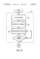
- FIG. 16 is a flowchart illustrating the steps used in the application of a median filter to the image of FIG. 10;
- FIG. 17 is an enlarged pictorial representation of a portion of the image of FIG. 10, illustrating the application of the median filter;
- FIG. 18 demonstrates the resulting image after application of a median filter, a process known herein as blobifying, to the scanned image of the example text, which tends to render character strings as a single set of connected pixels;
- FIG. 19 shows a subsequent step in the process, in which lines of white pixels are added to the blurred image to clearly delineate a line of character strings from adjacent lines of character strings;
- FIG. 20 is a flowchart illustrating the steps required to add the white lines of FIG. 19;
- FIGS. 21A and 21B are flowcharts representing the procedure which is followed to segment the image data in accordance with the blurred image of FIG. 18;
- FIG. 22 shows the sample text with bounding boxes placed around each word group in a manner which uniquely identifies a subset of image pixels containing each character string;
- FIGS. 23A and 23B illustrate derivation of a single independent value signal, using the example word "from", which appears in the sample image of example text;
- FIG. 24 illustrates the resulting contours formed by the derivation process illustrated in FIGS. 23A and 23B;
- FIG. 25 illustrates the steps associated with deriving the word shape signals
- FIGS. 26A, 26B, 26C and 26D illustrate derivation of a single independent value signal, using the example word "from";
- FIGS. 27A, 27B, 27C and 27D illustrate derivation of a single independent value signal, using the example word "red", which does not appear in the sample image of example text;
- FIG. 28 shows a simple comparison of the signals derived for the words “red” and “from” using a signal normalization method
- FIGS. 29A, 29B, and 29C illustrate the details of the discrepancy in font height, and the method for normalization of such discrepancies
- FIG. 30 is a flowchart detailing the steps used for one method of determining the relative difference between word shape contours
- FIG. 31 is a flowchart detailing the steps of a second method for determining the relative difference between word shape contours
- FIGS. 32A and 32B are respective illustrations of the relationship between the relative difference values calculated and stored in an array, for both a non-slope-constrained and a slope-constrained comparison.
- FIG. 33 is a block diagram of a preferred embodiment of an apparatus according to the invention for detecting function words in a scanned document image without first converting the document image to character codes;
- the Appendix contains source code listings for a series of image manipulation and signal processing routines which have been implemented to demonstrate the functionality of the present invention. Included in the Appendix are four sections which are organized as follows:
- Section A beginning at page 1, comprises the declarative or "include” files which are commonly shared among the functional code modules;
- Section B beginning at page 26, includes the listings for a series of library type functions used for management of the images, error reporting, argument parsing, etc.;
- Section C beginning at page 42, comprises numerous variations of the word shape comparison code, and further includes code illustrating alternative comparison techniques than those specifically cited in the following description;
- Section D beginning at page 145, comprises various functions for the word shape extraction operations that are further described in the following description.
- the invention is based upon the recognition that scanned image files and character code files exhibit important differences for image processing, especially in data retrieval.
- the method of a preferred embodiment of the invention capitalizes on the visual properties of text contained in paper documents, such as the presence or frequency of linguistic terms (such as words of importance like "important", “significant”, “crucial”, or the like) used by the author of the text to draw attention to a particular phrase or a region of the text; the structural placement within the document image of section titles and page headers, and the placement of graphics; and so on.
- a preferred embodiment of the method of the invention is illustrated in the flow chart of FIG. 1, and an apparatus for performing the method is shown in FIG. 2.
- the invention provides a method and apparatus for automatically excerpting semantically significant information from the data or text of a document based on certain morphological (structural) image characteristics of image units corresponding to units of understanding contained within the document image.
- the excerpted information can be used, among other things, to automatically create a document index or summary.
- the selection of image units for summarization can be based on frequency of occurrence, or predetermined or user selected selection criteria, depending upon the particular application in which the method and apparatus of the invention is employed.
- bitmap workstation i.e., a workstation with a bitmap display
- system using both bitmapping and scanning would work equally well for the implementation of the methods and apparatus described herein.
- the method is performed on an electronic image of an original document 5, which may include lines of text 7, titles, drawings, figures 8, or the like, contained in one or more sheets or pages of paper 10 or other tangible form.
- the electronic document image to be processed is created in any conventional manner, for example, by a conventional scanning means such as those incorporated within a document copier or facsimile machine, a Braille reading machine, or by an electronic beam scanner or the like. Such scanning means are well known in the art, and thus are not described in detail herein.
- An output derived from the scanning is digitized to produce undecoded bit mapped image data representing the document image for each page of the document, which data is stored, for example, in a memory 15 of a special or general purpose digital computer data processing system 13.
- the data processing system 13 can be a data driven processing system which comprises sequential execution processing means 16 for performing functions by executing program instructions in a predetermined sequence contained in a memory, such as the memory 15.
- the output from the data processing system 13 is delivered to an output device 17, such as, for example, a memory or other form of storage unit; an output display 17A as shown, which may be, for instance, a CRT display; a printer device 17B as shown, which may be incorporated in a document copier machine or a Braille or standard form printer; a facsimile machine, speech synthesizer or the like.
- the identified word units are detected based on significant morphological image characteristics inherent in the image units, without first converting the scanned document image to character codes.
- the first phase of the image processing technique of the invention involves a low level document image analysis in which the document image for each page is segmented into undecoded information containing image units (step 20) using conventional image analysis techniques; or, in the case of text documents, preferably using the bounding box method described in copending U.S. patent application Ser. No. 07/794,392 filed concurrently herewith by Huttenlocher and Hopcroft, and entitled "Method for Determining Boundaries of Words in Text.”
- the locations of and spatial relationships between the image units on a page are then determined (step 25).
- an English language document image can be segmented into word image units based on the relative difference in spacing between characters within a word and the spacing between words. Sentence and paragraph boundaries can be similarly ascertained. Additional region segmentation image analysis can be performed to generate a physical document structure description that divides page images into labelled regions corresponding to auxiliary document elements like figures, tables, footnotes and the like. Figure regions can be distinguished from text regions based on the relative lack of image units arranged in a line within the region, for example. Using this segmentation, knowledge of how the documents being processed are arranged (e.g., left-to-right, top-to-bottom), and, optionally, other inputted information such as document style, a "reading order" sequence for word images can also be generated.
- image unit is thus used herein to denote an identifiable segment of an image such as a number, character, glyph, symbol, word, phrase or other unit that can be reliably extracted.
- the document image is segmented into sets of signs, symbols or other elements, such as words, which together form a single unit of understanding.
- Such single units of understanding are generally characterized in an image as being separated by a spacing greater than that which separates the elements forming a unit, or by some predetermined graphical emphasis, such as, for example, a surrounding box image or other graphical separator, which distinguishes one or more image units from other image units in the scanned document image.
- word units Such image units representing single units of understanding will be referred to hereinafter as "word units.”
- a discrimination step 30 is next performed to identify the image units which have insufficient information content to be useful in evaluating the subject matter content of the document being processed.
- One preferred method is to use the morphological function or stop word detection techniques disclosed in the copending U.S. patent application Ser. No. 07/794,190 filed concurrently herewith by D. Bloomberg et al., and entitled "Detecting Function Words Without Converting a Document to Character Codes".
- a binary image contains pixels that are either ON or OFF.
- Binary images are manipulated according to a number of operations wherein one or more source images are mapped onto a destination image. The results of such operations are generally referred to as images.
- a morphological operation refers to an operation on a pixelmap image (a source image), that uses a local rule at each pixel to create another pixelmap image, the destination image. This rule depends both on the type of the desired operation to perform as well as on the chosen structuring element.
- a structuring element refers to an image object of typically (but not necessarily) small size and simple shape that probes the source image and extracts various types of information from it via the chosen morphological operation.
- FIGS. 4 and 5 show SEs where a solid circle is a hit, and an open circle is a miss. The center position is denoted by a cross. Squares that have neither solid nor open circles are "don't cares"; their value in the image (ON or OFF) is not probed.
- a binary SE is used to probe binary images in a binary morphological operation that operates on binary input images and creates an output binary image. The SE is defined by a center location and a number of pixel locations, each normally having a defined value (ON or OFF).
- a solid SE refers to an SE having a periphery within which all pixels are ON.
- a solid 2 ⁇ 2 SE is a 2 ⁇ 2 square of ON pixels.
- a solid SE need not be rectangular.
- a horizontal SE is generally one row of ON pixels and a vertical SE is generally one column of ON pixels of selected size.
- a hit-miss SE refers to an SE that specifies at least one ON pixel and at least one OFF pixel.
- AND, OR and XOR are logical operations carried out between two images on a pixel-by-pixel basis.
- NOT is a logical operation carried out on a single image on a pixel-by-pixel basis.
- EXPANSION is scale operation characterized by a scale factor N, wherein each pixel in a source image becomes an N ⁇ N square of pixels, all having the same value as the original pixel.
- REDUCTION is a scale operation characterized by a scale factor N in a threshold level M.
- the value for the pixel in the destination image is determined by the threshold level M, which is a number between I and N 2 . If the number of ON pixels in the pixel square is greater or equal to M, the destination pixel is ON, otherwise it is OFF.
- EROSION is a morphological operation wherein a given pixel in the destination image is turned ON if and only if the result of superimposing the SE center on the corresponding pixel location in the source image results in a match between all ON and OFF pixels in the SE and the underlying pixels in the source image.
- An EROSION will give one pixel in the destination image for every match. That is, at each pixel, it outputs 1 if the SE (shifted and centered at that pixel) is totally contained inside the original image foreground, and outputs 0 otherwise.
- EROSION usually refers to operations using a SE with only hits and more generally matching operations with both hits and misses (often called a hit-miss transform).
- the term EROSION is used herein to include matching operations with both hits and misses, thus the hit-miss transform is the particular type of EROSION used herein.
- DILATION is a morphological operation wherein a given pixel in the source image being ON causes the SE to be written into the destination image with the SE center at the corresponding location in the destination image.
- the SEs used for DILATION typically have no OFF pixels.
- the DILATION draws the SE as a set of pixels in the destination image for each pixel in the source image.
- the output image is the union of all shifted versions of the SE translated at all 1-pixels of the original image.
- FillClip is a morphological operation where one image is used as a seed and is grown morphologically, clipping it at each growth step to the second image.
- a fillClip could include a DILATION followed by logically ANDing the DILATION result with another image.
- OPENING is a morphological operation that uses an image and a structuring element and consists of an EROSION followed by a DILATION. The result is to replicate the structuring element in the destination image for each match in the source image.
- CLOSING is a morphological operation using an image and a structuring element. It includes a DILATION followed by an EROSION of the image by a structuring element.
- a CLOSE of an image is equivalent to the bit inverse of an OPEN on the (bit inverse) background.
- UNION is a bitwise OR between two images. An intersection is a bitwise AND between two images.
- Blurring is a DILATION of an image by a structuring element(s) consisting of two or more hits.
- a mask refers to an image, normally derived from an original or source image, that contains substantially solid regions of ON pixels corresponding to regions of interest in the original image.
- the mask may also contain regions of ON pixels that do not correspond to regions of interest.
- references to DILATION may be in terms of DILATING the image or the image being DILATED (verb forms) or the image being subjected to a DILATION operation (adjective form). No difference in meaning is intended.
- Morphological operations have several specific properties that simplify their use in the design of appropriate procedures. First, they are translationally invariant. A sideway shift of the image before transforming does not change the result, except to shift the result as well. Operations that are translationally invariant can be implemented with a high degree of parallelism, in that each point in the image is treated using the same rule. In addition, morphological operations satisfy two properties that make it easy to visualize their geometrical behavior. First, EROSION, DILATION, OPEN and CLOSE are increasing, which means that if image 1 is contained in image 2, then any of these morphological operations on image 1 will also be contained in the morphological operation on image 2. Second, a CLOSE is extensive and OPEN is antiextensive.
- An image unit means an identifiable segment of an image such as a word, number, character, glyph or other units that can be extracted reliably and have an underlying linguistic structure.
- image unit with significant characteristics becomes a significant image unit in that it contains high value information which can be used for further processing of the document image.
- Significant characteristics of image units include a variety of classifiers such as length, width, location on a page of the document image, font, typeface and measurement by other parameters including, but not limited to: one or more cross-sections of a box (a cross-section being a sequence of ON or OFF pixels); a number of ascenders associated with an image unit; a number of descenders associated with an image unit; average pixel density in an image unit; a length of a topline contour of an image unit, including peaks and troughs; a length of a base contouring of the image units, including peaks and troughs; and the location of image units with respect to neighboring image units, e.g., vertical position and horizontal inter-image unit spacing.
- An image of a page of a document is scanned in step 302 and the image is segmented into image units in step 304 by using either a conventional image analysis techniques or by using first a technique to determine baselines of image units and then second a technique for providing bounding boxes around image units (see U.S. patent application Ser. No. 07/794,391 entitled "A Method of Deriving Wordshapes for Subsequent Comparison" by Huttenlocher et al.)
- a length and height of each image unit in the image is determined.
- Short image units are determined in step 308 as image units of no more than a predetermined number of characters, preferably three characters or less in length.
- image units which are not short image units are deleted from the image.
- the image is blurred or smeared in a horizontal direction although the image units are not smeared together. This can be accomplished for example by CLOSING the image with a horizontal structuring element such as the structuring element of length 5 (i.e., 5 pixels) shown in FIG. 6.
- the length of the horizontal structuring element used to blur the x-height characters in the image is dependent upon the width of the character type being used.
- other configurations of structuring elements may be used in the CLOSING operation to obtain the same smearing effect.
- the most efficient and effective way to smear characters of x-height is to use a horizontal structuring element as described above.
- a UNION of erosions is taken in step 314 of the image by using a set of ascender matching structuring elements such as those shown in FIGS. 4A-4F, and a set of descender matching structuring elements such as those shown in FIGS. 5A-5F.
- the UNION taken in step 314 provides optional noise elimination filtering, and the UNION will provide a seed from which to fill short image unit masks in a subsequent seed filling operation such as the fillClip operation of step 316.
- the UNION of step 314 acts on all image units remaining in the image (i.e., only short image units in this case) and since the UNION of erosions was taken using a set of ascender matching structuring elements and a set of descender matching structuring elements, the image units that will be filled are those containing ascender and/or descender characters, i.e., function words.
- the function words are identified in step 318 as those image units which are filled short image unit masks.
- step 320 a test occurs to determine whether a last page of the document has been scanned. If the last page has been scanned, then the method terminates at step 324, otherwise the page is incremented in step 322 and the incremented (next) page is scanned in step 302 whereupon the image (next page) is scanned and the previously described steps of the method are reiterated.
- all pages could be scanned and stored as bit map images in a memory prior to performing the function word identification procedures described above.
- the image segmentation step can also be performed prior to performing this method and the segmented image stored in memory.
- step 40 selected image units, e.g., the image units not discriminated in step 30, are evaluated, without decoding the image units being classified or reference to decoded image data, based on an evaluation of predetermined morphological (structural) image characteristics of the image units.
- the evaluation entails a determination (step 41) of the image characteristics and a comparison (step 42) of the determined image characteristics for each image unit with the determined image characteristics of the other image units.
- One preferred method for defining the image unit image characteristics to be evaluated is to use the word shape derivation techniques disclosed in the copending U.S. patent application Ser. No. 07/794,391 filed concurrently herewith by D. Huttenlocher and M. Hopcroft, and entitled “A Method of Deriving Wordshapes for Subsequent Comparison,” Published European Application No. 0543594, published May 26, 1993.
- At least one, one-dimensional signal characterizing the shape of a word unit is derived; or an image function is derived defining a boundary enclosing the word unit, and the image function is augmented so that an edge function representing edges of the character string detected within the boundary is defined over its entire domain by a single independent variable within the closed boundary, without individually detecting and/or identifying the character or characters making up the word unit.
- a bitmap of an image is initially directed to a segmentation system 712, in which words, or character strings, or other multi-character units of understanding, will be derived.
- the image bitmap passes through skew detector 714, which determines the angle of orientation of text in the image.
- skew detector 714 determines the angle of orientation of text in the image.
- text baseline processor 716 uses information about the orientation of the image, and the image itself, at text baseline processor 716, toplines and baselines of the text are determined, so that upper and lower boundaries of lines of text within the image are identified.
- blobify the function referred to as "blobify” is performed, which operates on the image so that each word group in a line may be treated as a single unit.
- word “symbol string” or “character string” refers to a set of connected alphanumeric or punctuation elements, or more broadly, signs or symbols which together form a single unit of semantic understanding. It will be appreciated that these terms may also be used to refer to the images thereof. Such single units of understanding are characterized in an image as separated by a spacing greater than that which separates the elements, signs or symbols forming the unit.
- a set of white lines are added at block 720, to clearly separate adjacent lines of text.
- the white lines are based on baseline determinations provided by processor 716. Using this information, i.e., the blobified words, which are clearly separated from adjacent words and words in adjacent lines, a bounding box is defined about the word at block 722, thereby identifying and enclosing the word.
- word shape signal computer 724 derives a word shape signal representing the individual words in the image, based on the original image and the bounding box determinations. This information is then available for use at a word shape comparator 726, for comparing word shape signals representative of known words from a word shape dictionary 728, with the as yet unidentified word shape signals.
- word shape comparator 726 may be used to compare two or more word shapes determined from image 710. More importantly, word shape comparator 726 is not limited to the comparison of word shapes from unrecognized strings of characters to known word shapes. In a simplified context, comparator 726 is merely an apparatus for comparing one word shape against another to produce a relative indication of the degree of similarity between the two shapes.
- a method accomplishing this technique includes the following steps. Once orientation of the image is established and line spacing and word group spacing is established, each word can be surrounded by a bounding box.
- a reference line is then created extending through the character string image.
- the reference line may be a block having a finite thickness ranging from two-thirds of the x height to one-third of the x height, or in fact it may have a zero width.
- the distance from the reference line to the upper edge of the text contour or bounding box is measured in a direction perpendicular to the reference line. Similarly, measurements may be made from the reference line to the lower bounding box edge or to the text contour along the lower portion of the word, whichever is closer.
- the signal can be considered a single independent variable or one dimensional signal. Either or both of these sets of values may be used to describe the word shape. Additionally, although possibly less desirable, it is well within the scope of this method to measure the distance of a perpendicular line drawn from the top of the bounding box or the bottom of the bounding box, to the first contact with the word or the reference line, as desired.
- the method may also be considered mathematically.
- image data i(x,y) which in one common case could be an array of image data in the form of a bitmap
- a character set is identified in one of many methods, perhaps as described above, which defines a boundary enclosing the selected symbol string within a subset of the array of image data.
- an edge signal e(x,y) which represents the edges of i(x,y) detected within the closed boundary, is derived.
- the edge signal is augmented by adding additional data to i(x,y) so that e(x,y) is a signal e'(x,y) defined over its entire domain with respect to a single dimension or variable within the closed boundary.
- One, two, or more signals may be derived from e'(x,y) which are each one dimensional signals g'(t), where g is a function of parameter t which is a reference frame dependent parameter.
- the mathematical process used for the derivation of the one dimensional signal is essentially reversible up to the information it contains, e.g., a bitmap may be reconstructed from the upper and lower bitmap contours. It will be noted that if the reference has a finite thickness and is therefore taken out of the image, that portion of the image is not identifiable, however, if it has a zero width the information still remains.
- a recognition dictionary, or look up table of word shapes, can clearly be created through use of the described process.
- the process can be operated on using either scanned words as the source of the information, or in fact, they can be computer generated for a more "perfect" dictionary.
- FIG. 10 a sample image, taken from a public domain source is shown, having several lines of text contained therein.
- FIG. 10 demonstrates approximately how the image would appear on the page of text
- FIG. 11, shows a scanned image of the page, which demonstrates an enlargement of the image of a bitmap that would present problems to known OCR methods.
- the image of the word 50a "practitioner" in the first line of the text image it may be seen that several of the letters run together.
- circled and numbered 52 noise is present.
- the word “practitioner's” circled and numbered 54, the running together of a punctuation mark and a letter is further noted.
- skew detector 714 may be implemented using a general method for determining the orientation of the text lines in the image. This method looks at a small number of randomly selected edge pixels (defined as a black pixel adjacent to at least one white pixel), and for each edge pixel considers, at FIG. 12A, a number of lines, 56a, 56b, 56c being examples, extending from the pixel at evenly spaced angular increments over a specified range of angles.
- the edge pixels are selected randomly from the set of all image pixels by the function RandomEdgePixel() (Appendix, page 243).
- 12A (see lines 56a, 56b, 56c), 12B (see lines 58a, 58b, 58c) and 12C (see lines 60a, 60b, 60c) represent a series of increasingly smaller angular ranges over which the above mentioned technique is applied to illustrative edge pixels to accurately determine the angular orientation of the text within the image.
- skew detector 714 traces the path of each line, determining the lengths, in pixels, of strings of successive black pixels which are intersected by the line.
- an average black pixel string length is calculated by summing the lengths of the individual strings, and dividing the sum by the total number of distinct strings which were found.
- Curve A is a graphical representation of the summation/averaging function over each of a series of angled lines extending from the edge pixel, and spread over a range from 0 to 2 ⁇ radians.
- a coarse skew angle is identified. Subsequently, it is necessary to more closely determine the skew angle of the text. This is accomplished by utilizing a number of lines which extend from a randomly selected edge pixel, where the lines differ by smaller angular increments, and the angular range is centered about the coarse skew angle.
- the fine skew angle may be determined by analyzing the total number of black pixels contained along a predetermined length of the lines. More specifically, the number of pixels over a unit distance are plotted as curve B on FIG. 12D, and the fine skew angle is determined by identifying the maxima of the curve.
- the skew angle may be determined as indicated by the NewFine() function (Appendix, page 245), which determines the skew angle using multiple iterations of the procedure described with respect to the fine angle determination. As indicated by FIGS. 12A, 12B, and 12C, each iteration would also use lines covering an increasingly smaller angular range, until a desired skew angle accuracy is reached. In the implementation illustrated by FIGS. 12A, 12B, and 12C, the desired accuracy is achieved by a series of three iterations, each using a series of 180 distinct angles about the selected edge pixel.
- text baseline processor 716 identifies the characteristic lines, upper topline and lower baseline, of each line of text.
- the process steps executed by text baseline processor 716 are illustrated in detail in FIGS. 14A and 14B.
- the histogram of FIG. 13A shown to the left along the image, is derived by examining lines, at the resolution of the image, and oriented parallel to the skew orientation of the image, as defined by the previously determined skew angle. These parallel lines spanning the image are used to determine the number of black pixels intersected by each of the lines. Along lines passing through inter text line spaces, no black pixels should be intercepted, while along lines through the text, large numbers of black pixels should be intercepted.
- BaseLines() (Appendix page 160), first finds the coordinates of a "main" line, block 142, constructed through the center of the image and perpendicular to the text lines, as determined by the skew angle passed to the function as shown by block 140.
- Line Engine Procedure 144 is executed, where by proceeding along the main line from one end to the other, at a series of points along the main line, perpendicular branch lines are constructed which extend outwardly from the main line for a fixed distance, block 146.
- branch lines the number of black vertical edge pixels are counted, block 148, and the number of black pixels intersected by the lines are counted, block 150, and summed for the opposing pairs of lines, block 152.
- Black vertical edge pixels are defined as black pixels having a white neighboring pixel at either the upper or lower neighboring pixel position.
- LineEngine()procedure 144 is repeated until all points, and associated branch lines, along the main line have been processed, as determined by decision block 154. An x-height value may be returned from this procedure, which will subsequently be used by the word shape computer 724.
- the counts for all the branch lines are analyzed to determine the branch line pairs having the highest ratio of black vertical edge pixels to black pixels.
- those lines having the highest percentages would correspond to lines passing along the upper and lower edges of the characters which form the text lines.
- a definite distinction exists between those branch lines having a high vertical edge pixel ratio, line 82, and those having a low ratio, line 84.
- Application of a filter mask and comparison of the maximum peaks within the mask enables the identification of those lines which represent the text toplines and baselines, for example, line 82.
- a flag which is cleared at the start of each branch line analysis, may be set whenever a series of five sequential black pixels are detected along the line. This test would assure that small noise or image artifacts are not recognized as baselines due to a high vertical edge pixel ratio.
- step 162 may be utilized to identify the upper and lower baselines of a baseline pair, based upon the slope of the BL histogram curve. It is important to note that there is little additional processing associated with the identification step as the histogram information was collected previously during step 150.
- a verification step block 164, is executed to verify that the baseline pairs are separated by more than a minimum distance, the minimum distance being established by calculating the average line pair separation for all line pairs in the image. After verification, the valid baseline information is stored by output block 166 for later use by the white line addition and segmentation blocks, 18 and 720, respectively.
- FIG. 15 shows the result of the baseline determination on the example image of the sample text, showing that baseline pair, baseline and topline B n and B n ', respectively, have been located on the image, indicating those portions of the image in which a predominant portion of the text occurs. While some portions of the character ascender strokes are outside the baselines, no detriment to the remainder of the process is noted. Of course, a smaller threshold value might enable the system to capture more of the ascending strokes.
- the next process step is a word group isolation step.
- a filter 718 is applied to a copy of the image which results in an image that tends to render the word into blobs distinguishable from one another.
- the filter is applied with a small window, to each area, to render as black those areas that are partly black.
- the blobify function (Appendix page 165) first initializes mask variables which establish the mask size and angle, block 180, and then processes the upper scanline to initialize the data array, block 182.
- FIG. 17 which illustrates some examples of the filter process, has a mask window 200 placed over a portion of the image. For example, with a twenty percent threshold and a generally rectangular mask having twenty-one pixels, arranged at an angel approximately equal to the skew determined for the text, the result of filtering in window 200 would be the setting of pixel 204 to black. Similarly, window 206, which primarily lies within the intercharacter spacing between the pixel representations of the letters "r" and "o", would cause pixel 208 to be set to black.
- window 210 which lies in the region between word groups, would not have a sufficient number of black pixels present within the window to cause pixel 212 to be set to black.
- the size, shape and orientation of mask window 200 is optimized to reduce the filling in between text lines, while maximizing the fill between letters common to a single word.
- the result of the median filtering is that the relatively small spacing between characters in a word generally becomes inconsequential, and is filled with black pixels. Words become a single connected set of pixels, i.e., no white spaces completely separate characters in a single word.
- the relatively large spacing between character strings or between words is a larger space outside of the ability of the filter to turn into black, and therefore serves to distinguish adjacent symbol strings.
- white line addition 720 superimposes upon the blobified image of FIG. 12 a series of white pixel lines to make certain that lines of text are maintained separately from adjacent lines of text (i.e., no overlapping of the filtered text lines).
- FIGS. 18 and 19 noting the circled areas 258 and 258', a combination of an ascender and descender has resulted in an interline merging of two words.
- the text line overlap illustrated in area 258 of FIG. 18 is exactly what is eliminated by superimposing the white lines on the blobified or filtered image.
- FIG. 19 shows the result of white line addition to the blobified image of FIG. 18.
- white line addition block 720 begins by initializing variables in step 280 and subsequently reads in the topline location from the baseline information of the first text line.
- the topline information is discarded, block 282, and the next baseline and topline locations are popped from the storage stack or list, blocks 284 and 286, respectively.
- this baseline-topline pair respectively represents the bottom and top of adjacent text lines.
- step 288 the point lying at the center of the pair is located to provide a starting point for the white lines which are drawn from the center of the image in an outward direction.
- the endpoints of the white lines are calculated in step 290, using the skew angle determined by skew detector 714 of FIG. 7.
- White lines are drawn or superimposed on the blobified image at step 292, and the process is continued until all text lines have been effectively separated, as controlled by test block 294.
- the position of bounding boxes about each connected set of pixels formed in the blobify step may be determined.
- Bounding boxes are placed only about those connected components or words that are in a text line lying between the superimposed white lines.
- the bounding boxes are placed at the orientation of the text line, by identifying the extreme points of each group of connected pixels in the direction of the text line, and in the direction orthogonal to the text line, as opposed to the image coordinate system.
- This operation is performed by the function FindBorders(), (Appendix, page 172).
- the FindBorders function steps through all pixels within the image to find the bounding boxes of the connected characters (Paint Component), to determine the coordinates of the upper left corner of each box, as well as the length and width of the box.
- segmentation step 1022 begins by placing a white border completely around the filtered image, step 1300. This is done to avoid running outside the edge of the array of image pixels.
- pixel and line counters, x and y, respectively are initialized to the first pixel location inside the border.
- the ReadPixel procedure block 1304
- the pixel color black or white
- the PaintComponent() procedure is called and begins by storing the location of the black pixel in a queue, block 1308.
- the pixel is set to white and the boundaries of the box, surrounding the connected pixels or components, are updated, blocks 1310 and 1312, respectively.
- adjoining black pixels are set to white, block 1314, and the locations of the black pixels are added to the end of the queue, block 1316.
- the queue pointers are tested to determine if the queue is empty. If not empty, the next pixel in the queue is retrieved, block 1320, and processing continues at block 1312. Otherwise, if the queue is empty, all of the connected black pixels will have been set to white and the box boundaries will reflect a box which encompasses the connected components. Subsequently, the boundaries of the box which encompasses the word segment are verified and may be adjusted to an orthogonal coordinate system oriented with respect to the skew of the text lines, block 1322.
- the looping process continues at block 1324 which checks pixel counter x to determine if the end of the scanline has been reached, and if not, increments the counter at block 1326 before continuing the process at block 1304. If the end of the scanline has been reached, pixel counter x is reset and scanline counter y is incremented at block 1328. Subsequently, block 1330 checks the value of scanline counter y to determine if the entire image has been processed. If so, processing is completed. Otherwise, processing continues at block 1304 for the first pixel in the new scanline.
- the extremities of the connected character image define the bounding box.
- Noise marks are determined: 1) if a bounding box corner is outside the array of image pixels (Appendix, page 171); 2) if a box spans multiple text lines in the array (Appendix 229), or lies completely outside a text line; 3) if boxes are too small compared to a reference ⁇ , in either or both longitudinal or latitudinal directions, and accordingly are discarded.
- Noise marks 70a and 72 and others will not be considered words.
- the OnABaseline() function (Appendix, page 229) is an example of a function used to eliminate those boxes lying outside of the baseline boundaries.
- the derived signal is referred to as a word shape contour.
- the shape contour for each word is determined using the MakeShell() function (Appendix, page 228). As illustrated in FIG. 23A, this function first moves along the top of each bounding box, and starting with each pixel location along the top of the box, scans downward relative to the page orientation, until either a black pixel, or the bottom of the box, is reached. A record of the set of distances d between the top of the box and the black pixel or box bottom is maintained.
- the set of distances d, accumulated over the length of the box, constitutes the top raw contour of the word shape.
- a bottom raw contour is produced in a similar manner as illustrated in FIG. 23B, for the same word depicted in FIG. 23A, by sequentially moving across the bottom of the box, and looking in an upwards direction, for either the first black pixel or the top of the bounding box.
- one or more reference lines are established through each word.
- the data representing the symbol string is augmented, so that it is defined over the range of the symbol string.
- a blackout bar which may have a finite thickness or a zero thickness is constructed through the word, preferably having an upper limit or reference line at approximately two thirds of the x height, and a lower limit or reference line at approximately one-third of the x height (which was determined at the baseline determination step).
- a set of measurements is derived, for the distance d between the upper or lower edge of the bounding box, and the word, or the nearer of the reference line's closer edge of the black out bar.
- the calculation's measurements are made at the resolution of the image. With reference to FIG. 26A, where the calculation's measurements are illustrated pictorially, it can be seen that the reference lines serve to allow the signal that will ultimately be derived from this step to be defined at every sampling position over the length of the word.
- the calculation's measurements of d are actually generated from the contour data derived in accordance with FIGS. 23A, 23B previously collected, and are adjusted to limit the distance d with either the upper or lower edge of the blackout bar as indicated.
- measurements are made from the upper line of the bounding box to the upper reference line of the word, although this is not a requirement. Thus, for example, the measurement could alternatively be made from the reference line to either the upper or lower bounding line, or the character.
- FIG. 26B better shows how the set of measurements is used to form the signal output from block 104.
- the contour is represented as a set of measurements distance d', relative to the reference line. Measurement d' is therefore derived from the measurements shown in FIG. 26A, which designate the stopping point of line d, and the known position of the black out bar. Calculating the distance relative to the reference line enables scaling of the word shape contours to a common x height, thereby facilitating any subsequent comparison of the shapes.
- the distances d' represent a measurement from the reference line or blackout bar to the outer limits of the letter, and in the absence of a letter, provide a zero measurement. These measurement might be derived directly, but the proposed indirect methods appear easier to implement.
- FIGS. 26C and 26D show that the sets of d' values can be plotted on a graph to form a one dimensional signal or curve representing the word shape. Details of the contour determination are contained in the function StoreOutlinePair() beginning in the Appendix at page 255.
- FIG. 24 is an image of the contour locations as established for the text sample of FIG. 10. It is important to note the informational content of FIG. 24, where, for the most part, it is relatively easy to recognize the words within the passage by their contours alone.
- a stepwise process might be used, which first will derive the upper word shape signal or contour, second will derive the lower word shape signal or contour, and thirdly derive a word shape signal central contour (from the reference line towards the word or bounding box), in a prioritized examination of word shape, as required.
- the word "from” is fairly uniquely identifiable from its upper portion only.
- the word “red” is less uniquely identifiable from its upper portion, since it may be easily confused with the word "rod”, and perhaps the word "rad”.
- the determined morphological image characteristic(s) or derived image unit shape representations of each selected image unit are compared, as noted above (step 42), either with the determined morphological image characteristic(s) or derived image unit shape representations of the other selected image units (step 42A), or with predetermined/user-selected image characteristics to locate specific types of image units (step 42B).
- the determined morphological image characteristics of the selected image units are advantageously compared with each other for the purpose of identifying equivalence classes of image units such that each equivalence class contains most or all of the instances of a given image unit in the document, and the relative frequencies with which image units occur in a document can be determined, as is set forth more fully in the copending U.S. patent application Ser. No.
- Image units can then be classified or identified as significant according the frequency of their occurrence, as well as other characteristics of the image units, such as their length. For example, it has been recognized that a useful combination of selection criteria for business communications written in English is to select the medium frequency word units.
- the method for determining the frequency of words without decoding the document is shown in FIG. 8.
- the image is segmented into undecoded information containing image units (step 820) by using the method described above or by finding word boxes.
- Word boxes are found by closing the image with a horizontal SE that joins characters but not words, followed by an operation that labels the bounding boxes of the connected image components (which in this case are words).
- the process can be greatly accelerated by using 1 or more threshold reductions (with threshold value 1), that have the effect both of reducing the image and of closing the spacing between the characters.
- the threshold reduction(s) are typically followed by a closing with a small horizontal SE.
- the connected component labeling operation is also done at the reduced scale, and the results are scaled up to full size.
- the disadvantage of operating at reduced scale is that the word bounding boxes are only approximate; however, for many applications the accuracy is sufficient.
- the described method works fairly well for arbitrary text fonts, but in extreme cases, such as large fixed width fonts that have large inter-character separation or small variable width fonts that have small inter-word separation, mistakes can occur.
- the most robust method chooses a SE for closing based on a measurement of specific image characteristics. This requires adding the following two steps:
- locations of and spatial relationships between the image units on a page are determined (step 825). For example, an English language document image can be segmented into word image units based on the relative difference in spacing between characters within a word and the spacing between words. Sentence and paragraph boundaries can be similarly ascertained. Additional region segmentation image analysis can be performed to generate a physical document structure description that divides page images into labelled regions corresponding to auxiliary document elements like figures, tables, footnotes and the like. Figure regions can be distinguished from text regions based on the relative lack of image units arranged in a line within the region, for example.
- image unit is thus used herein to denote an identifiable segment of an image such as a number, character, glyph, symbol, word, phrase or other unit that can be reliably extracted.
- the document image is segmented into sets of signs, symbols or other elements, such as words, which together form a single unit of understanding.
- Such single units of understanding are generally characterized in an image as being separated by a spacing greater than that which separates the elements forming a unit, or by some predetermined graphical emphasis, such as, for example, a surrounding box image or other graphical separator, which distinguishes one or more image units from other image units in the document image.
- word units Such image units representing single units of understanding will be referred to hereinafter as "word units.”
- a discrimination step 830 is next performed to identify the image units which have insufficient information content to be useful in evaluating the subject matter content of the document being processed by using the technique described above.
- step 840 selected image units, e.g., the image units not discriminated in step 830, are evaluated, without decoding the image units being classified or reference to decoded image data, based on an evaluation of predetermined image characteristics of the image units.
- the evaluation entails a determination (step 841) of the image characteristics and a comparison (step 842) of the determined image characteristics for each image unit with the determined image characteristics of the other image units.
- One preferred method for defining the image unit morphological image characteristics to be evaluated is to use the word shape derivation techniques previously discussed. At least one, one-dimensional signal characterizing the shape of a word unit is derived; or an image function is derived defining a boundary enclosing the word unit, and the image function is augmented so that an edge function representing edges of the character string detected within the boundary is defined over its entire domain by a single independent variable within the closed boundary, without individually detecting and/or identifying the character or characters making up the word unit.
- the determined image characteristic(s), e.g., the derived image unit shape representations of each selected image unit are compared, as noted above (step 841), with the determined image characteristic(s)/derived image unit shape representations of the other selected image units for the purpose of identifying equivalence classes of image units (step 850), such that each equivalence class contains most or all of the instances of a given word in the document.
- the equivalence classes are thus formed by clustering the image units in the document based on the similarity of image unit classifiers, without actually decoding the contents of the image units, such as by conversion of the word images to character codes or other higher-level interpretation. Any of a number of different methods of comparison can be used.
- One technique that can be used, for example, is by correlating the raster images of the extracted image units using decision networks, such technique being described for characters in a Research Report entitled "Unsupervised Construction of Decision networks for Pattern Classification” by Casey et al., IBM Research Report, 1984, herein incorporated in its entirety.
- comparisons of different degrees of precision can be performed.
- useful comparisons can be based on length, width or some other measurement dimension of the image unit (or derived image unit shape representation e.g., the largest figure in a document image); the location of the image unit in the document (including any selected figure or paragraph of a document image, e.g., headings, initial figures, one or more paragraphs or figures), font, typeface, cross-section (a cross-section being a sequence of pixels of similar state in an image unit); the number of ascenders; the number of descenders; the average pixel density; the length of a top line contour, including peaks and troughs; the length of a base contour, including peaks and troughs; and combinations of such classifiers.
- One way in which the image units can be conveniently compared and classified into equivalence classes is by comparing each image unit or image unit shape representation when it is formed with previously processed image units/shape representations, and if a match is obtained, the associated image unit is identified with the matching equivalence class. This can be done, for example, by providing a signal indicating a match and incrementing a counter or a register associated with the matching equivalence class. If the present image unit does not match with any previously processed image unit, then a new equivalence class is created for the present image unit.
- each equivalence class can be linked together, and mapped to an equivalence class label that is determined for each equivalence class.
- the number of entries for each equivalence class can then be merely counted.
- the selection process can be extended to phrases comprising identified significant image units and adjacent image units linked together in reading order sequence.
- the frequency of occurrence of such phrases can also be determined such that the portions of the source document which are selected for summarization correspond with phrases exceeding a predetermined frequency threshold, e.g., five occurrences.
- a predetermined frequency threshold e.g., five occurrences.
- the specification of the image characteristics for titles, headings, captions, linguistic criteria or other significance indicating features of a document image can be predetermined and selected by the user to determine the selection criteria defining a "significant" image unit.
- titles are usually set off above names or paragraphs in boldface or italic typeface, or are in larger font than the main text.
- a related convention for titles is the use of a special location on the page for information such as the main title or headers. Comparing the image characteristics of the selected image units of the document image for matches with the image characteristics associated with the selection criteria, or otherwise recognizing those image units having the specified image characteristics permits the significant image units to be readily identified without any document decoding.
- One technique that can be used is by correlating the raster images of the extracted image units using decision networks, such technique being described in a Research Report entitled "Unsupervised Construction of Decision networks for Pattern Classification” by Casey et al., IBM Research Report, 1984, herein incorporated in its entirety.
- Preferred techniques that can be used to identify equivalence classes of word units are the word shape comparison techniques disclosed in U.S. patent application Ser. Nos. 07/796,119 and 07/795,169, filed concurrently herewith by Huttenlocher and Hopcroft, and by Huttenlocher, Hopcroft and Wayner, respectively, and entitled, respectively, "Optical Word Recognition By Examination of Word Shape,” Published European Application No. 0543592, published May 26, 1993, and "Method for Comparing Word Shapes.”
- U.S. patent application Ser. No. 07/795,169 discloses, with reference to FIG. 7, one manner in which a comparison is performed at word shape comparator 726.
- the comparison is actually several small steps, each of which will be described.
- FIG. 28 generally, the two word shape signals, one a known word, the other for an unknown string of characters are compared to find out whether they are similar.
- signal R is the upper contour of the word "red”
- signal F is the upper contour of the word "from”.
- relatively few signals could be expected to be exactly identical, given typical distinctions between character fonts, reproduction methods, and scanned image quality.
- the word shape signals to be compared may be scaled with respect to one another, so that they have the same x-heights. This is achieved by determining the x-height of the pair of word shape contours to be compared. Once determined, the ratios of the x-heights are used to determine a scale factor to be applied to one of the contours. As the x-height is a characteristic measurement for fonts, it is used to determine the scaling factor in both the horizontal and vertical directions. An example of the scaling operation is found in the fontNorm.c file beginning at line 172, where the StoreOutlinePair() function carries out the scaling operation in both the x and y, horizontal and vertical, directions.
- the shape signals may be compared without normalization and a weighing factor imposed upon the portion of the measured difference due to the unequal lengths. Furthermore, the amplitude or height of the signals has been normalized to further reduce the impact of the font size on the word shape comparison.
- each of the shape signals are normalized based upon a common relationship between the ascender and descender heights and the x-height of the text characters.
- the actual ascender heights of characters printed with supposedly similar font size, or what is now an appropriately scaled font size may be slightly different. This occurs as a result of type faces or fonts which are small on body or large on body, implying that similar characters exhibit variations in height across fonts that are the same size, for example 24 point fonts.
- 29A represents the difference in ascender height for two occurrences of the letter "h.”
- distance d 2 illustrates a similar difference between the heights of the letter "f" in FIG. 29B.
- the typical character may be broken into three sections, ascender portion 390, x-height portion 392, and descender portion 394.
- the relative heights of these sections are illustrated as c, a, and b, respectively.
- the normalization operation applied to the shape contours is found in the fontNorm.c module, beginning at page 183 of the Appendix.
- ⁇ string is the difference value between the two signals
- f(x) is the known signal
- g'(x) is the unknown signal.
- the difference could be examined and if it is close to zero, such would be indicated that there would be almost no difference between the two signals. However, the greater the amount of difference, the more likely that the word was not the same as the word to which it was being compared.
- step 410 the contour for the first word shape is retrieved from memory, and subsequently, the second word shape is retrieved by step 412.
- step 414 the centers of gravity of the word shapes, defined by the upper and lower contours. The purpose of this step is to align the centers of the word contours to reduce the contour differences that would be attributable solely to any relative shift between the two sets of contours being compared.
- the center of gravity is determined by summing the areas under the curves (mass) and the distances between the contours (moments) which are then divided to give an indication of the center of gravity for the upper and lower contour pair.
- the relative shift between the pairs is determined, step 416, and the contours are shifted prior to calculating the difference between the contours.
- the shifting of the contours is necessary to reduce any error associated with the establishment of the word shape boundaries and computation of the word shapes at block 724 of FIG. 7.
- Step 418 handles those regions lying outside the overlapping range of the shifted contour pairs, determining the difference against a zero amplitude signal in the non-overlapping regions. This is done by summing the squared values of the upper and lower contours at the non-overlapping ends of the contours. Subsequently, the overlapping region of the contours are compared, step 420.
- the difference in this region is determined as the sum of the squared differences between the upper curves and the lower curves, as shown in the function L2Norm() on page 100 of the Appendix.
- the values returned from steps 418 and 420 are added to determine a sum of the differences over the complete range defined by the shifted contours. This value may then be used as a relative indication of the similarity between the contour pairs for the two word shapes being compared.
- FIG. 31 depicts the general steps of the dynamic warping method
- the method relies on the use of a difference array or matrix to record the distances between each point of the first contour and points of the contour to which it is being compared.
- the process is similar for all of the measures which may be applied in the comparison.
- the organization of the code is such that a data structure is used to dynamically control the operation of the various comparison functions.
- the structure DiffDescriptor the declaration for which is found on page 9 of the Appendix (see diff.h), contains variables which define the measure to be applied to the contours, as well as, other factors that will be used to control the comparison.
- each measure implements a comparison technique, however, each is optimized for a specific type of dynamic comparison, for example, a slope limited dynamic warp having a non-unitary centerweight and a topToBottom weight greater than one.
- the first level of selection enables the use of a slope-constrained warping function for comparison, an unconstrained warp, or a simple, non-warped, comparison.
- the warp comparison methods there are both separate comparison functions, where the top and bottom contours are warped independently, and parallel comparison functions, where the warp is applied to both the top and bottom contours simultaneously. Specific details of the comparison functions are generally contained within the newMatch.c file beginning at page 101 of the Appendix.
- the dynamic warping process starts by allocating space for the path/distance array, step 450, which will hold the distance values generated during the comparison and warping of one word shape contour with respect to another.
- the border regions of the array must be initialized as the process used by all the warping measures is an iterative process using data previously stored in the array for the determination of the cumulative difference between the contours.
- the array borders are initialized. Initialization of the first row of the array entails the determination of the square of the difference between a first point on the first contour and each point on the second contour. Subsequent to border initialization, the column and row index values, L1 and L2, respectively, are reset to 1 to begin processing the individual, non-border, points along the contours.
- Processing of the contours proceeds at steps 458 through 464, where the difference in distance between each point along the second contour, with respect to a point on the first contour is calculated. Moreover, this difference, or distance, is calculated and then summed with a previously determined difference value. In addition, some of the previously determined difference values may be weighted differently, for example, in one embodiment weights of the difference values along the array diagonal may be modified by a centerWeight weighing factor.
- the distance (rest) is calculated as the sum of the squares of the differences between a point on the first contour and a point on the second contour, over the upper and lower contours, where the top contour difference is weighted by the topToBottom variable.
- This distance (rest) is used in subsequent iterations to determine the horizontal, vertical and diagonal difference values in the loop beginning at line 137 on page 103.
- the current distance value, represented by rest would be added to the previous values in the down, left, and down-left array positions, the down-left position value being the diagonal position which is weighted by the centerWeight factor as previously described. Referring to FIG.
- 32A which illustrates the positional relationship between a previously determined value X, at array location 502, and subsequent array locations
- the value X might be added to the difference values of subsequent locations to accumulate the total difference. calculations is shown.
- the value in location 502 would be used as the down value.
- the value of location 502 would be used as the center-weighted down-left, or diagonal, value.
- steps 458, 460, and 462 the process continues by selecting the smallest of the three values, step 464, for insertion into the current array position, step 466.
- the FMin() function from page 101 returns the minimum of the three values previously calculated, the value being inserted into the storage array pointed to by pointer dc.
- Step 468 controls the iterative processing of the points along the second contour by testing for the end of the contour, or swath.
- the index variables i and j are used in place of L1 and L2 to control the difference calculation loops.
- the swath is referred to as the bandwidth, and is determined by a desired bandwidth which is adjusted for the slope defined by the contour lengths (see page 102, lines 83-89).
- step 458 If no limit has been reached, processing for the next point would continue at step 458 after the value of L2 was incremented at step 470.
- decision step 472 controls the processing of each point along the first contour, in conjunction with incrementing step 474. Once all the points have been processed with respect to one another, as evidenced by an affirmative response in step 472, the relative difference score, best score, is contained in the farthest diagonal position of the array (L1, L2). Subsequently, the value determined at step 476 is returned as an indication of the dynamically warped difference between the contours being compared.
- the code implementation found in the NewMatch() function on page 103 of the Appendix has optimized the execution of the aforedescribed warping process by reducing the large two-dimensional array to a pair of linear arrays which are updated as necessary. Due to this modification, the minimum difference, or best score, for the warp comparison value is found in the last location of the one-dimensional array. Furthermore, the final difference value, dc, may be subsequently normalized to account for the length differences between the two sets of contours being compared. Finally, such a value might subsequently be compared against a threshold or a set of similarly obtained difference values to determine whether the contours are close enough to declare a match between the words, or to determine the best match from a series of word shape comparisons.
- the dynamic time warping process previously described may be altered to compare the difference values contained in the difference array to a threshold value on a periodic basis. Upon comparison, the process may be discontinued when it is determined that sufficient difference exists to determine that the contours being compared do not match one another, possibly saving valuable processing time.
- the sequential operation of word shape comparator 726 might be done in conjunction with sequential output from word shape computer 724, thereby enabling the parallel processing of a textual image when searching for a keyword.
- variable names refers to the array location which is down 2 rows and left one column
- d1L1 refers to the lower left diagonal array location
- d1L2 refers to the array location that is down one column on left 2 rows from the current array location.
- X may be added as the d1L2 value for the calculation of the cumulative difference value for array location 516.
- the slope constrained warping measure limits the warping path which can be followed during the generation of the cumulative difference value.
- the reason for implementing such a constraint is to prevent the warping process from removing, or compressing, a large area of one of the two contours being compared, without imposing a significant "cost" to such a compression.
- the method previously described with respect to the parallel warping process may also be implemented on only one pair of contours at a time, for example, the upper contours of two word shapes.
- the functions SepMatch() and SepCMatch() as found in the Appendix on pages 104 and 113, respectively, implement the separate matching measure in both the non-slope-constrained and slope-constrained fashions previously described.
- these measures separately calculate the difference between the top or bottom contours of a pair of wordshapes.
- the general implementation indicated for the measures in the code shows that these measures are typically used sequentially, first determining the warped difference for the top contours, and then adding to it the warped difference from the bottom contour comparison, resulting in a total difference for the wordshapes.
- cascaded comparison would entail, first, utilizing the upper contours of the words being compared to identify a word, or at least narrow the set of possible alternatives and, second, using the lower contour comparison to provide complete identification. It is believed that such an approach to word shape comparison operation 726 would considerably reduce processing time spent on identifying unknown word shapes by comparison to a dictionary of known word shapes, 728, as illustrated in FIG. 7. Important to the cascaded comparison, is the constraint that the top and bottom warps applied to the contours must be relatively equivalent. This requirement arises from the fact that the upper and lower curves have a relationship to a common word, and if this relationship is not maintained during the warp analysis, the accuracy of the comparison will be compromised.
- the dynamic warping technique may be applied as described, with the addition of a function suitable for accumulating the relative warp applied to the upper and lower curves in achieving the best match.
- a function suitable for accumulating the relative warp applied to the upper and lower curves in achieving the best match. For example, when a known, non-italicized word shape is compared to an unknown word shape, a shift in the warp applied to the upper curve relative to the lower curve could be indicative of an italicized word, however, the length of the warped region will remain the same for the top and bottom warps.
- Such a technique may prove useful in the identification of important words within a larger body of text, as these words are occasionally italicized for emphasis.
- the bandwidth factor controls the relative width of the signal band in which the warping signal will be constrained. More specifically, the band width limitation is implemented by defining a region about the array diagonal in which the warp path which traverses the array is constrained. The constraint is implemented by assigning large values to those areas outside of the band width, so as to make it highly unlikely that the path would exceed the constraint.
- topToBottom factor Another factor which was briefly mentioned is the topToBottom factor.
- the value of this variable is used to weight the difference value determined for the top contour warping process. Therefore, use of a number greater than one, will cause the upper contour difference to be weighted more heavily than the lower contour difference. A very large number would effectively eliminate the lower contour difference completely and, likewise, a zero value would eliminate the upper contour difference completely.
- This factor is generally considered important to enable the upper contour to be weighted in proportion to its information content, as it generally carries more information regarding the word than does the lower contour.
- the hillToValley ratio is a variable which is usually applied in situations when a known, or model, set of word shape contours is being compared against a set of word shape contours from an unknown image.
- the model set of contours is passed as the comparison measure functions, for example, NewMatch() on page 102 of the Appendix.
- the comparison functions commonly call the function SquareDifference() on page 101 of the Appendix to determine the sum of the squared difference. SquareDifference() applies the hillToValley ratio to the squared difference whenever it determines that the value of the model contour is less than the contour being compared.
- the result of applying a hillToValley value greater than one is that the relative "cost" of the difference when the model contour is less than the target contour is smaller than the same difference when the model contour is greater than the target contour.
- the basis for this type of weighing is that when comparing against a model contour, the comparison should treat those areas of the target contour that are subject to being " filled in" during a scanning or similar digitizing operation with less weight than regions not likely to be filled in, as evidenced by contour positions below the model contour. For instance, the regions where ascenders and descenders meet the body of the character are likely to be filled in during scanning, thereby causing the target contour to have a gradual contour in those regions, whereas the model contour would most likely have a defined peak or valley in these regions. Hence, the contour value of the model would be less than the contour value of the target, even though the characters may have been identical. Therefore, the hillToValley variable attempts to minimize the impact to the calculated difference value over these regions.
- the mathematical explanation of the word shape derivation process suggests that alternative methods of deriving the word shape signal exist. Some possible alternatives are the establishment of the one dimensional signal using an alternative coordinate scheme, for example polar coordinates. Another possibility is generation of signal g(t), where g(t) represents the direction from each contour point to the succeeding contour point, where t would represent the point number.
- comparisons of different degrees of precision can be performed.
- useful comparisons can be based on length, width or some other measurement dimension of the image unit (or derived image unit shape representation, e.g., the largest figure in a document image); the location or region of the image unit in the document (including any selected figure or paragraph of a document image, e.g., headings, initial figures, one or more paragraphs or figures), font, typeface, cross-section (a cross-section being a sequence of pixels of similar state in an image unit); the number of ascenders; the number of descenders; the average pixel density; the length of a top line contour, including peaks and troughs; the length of a base contour, including peaks and troughs; the location of image units with respect to neighboring image units; vertical position; horizontal inter-image unit spacing; and combinations of such classifiers.
- morphological image recognition techniques such as those disclosed in concurrently filed U.S. patent application Ser. No. 07/775,174, to Bloomberg et al., and entitled “Methods and Apparatus for Automatic Modification of Selected Semantically Significant Portions of a Document Without Document Image Decoding", can be used to recognize specialized fonts and typefaces within the document image.
- the above reference provides a method for automatically emphasizing selected information within the data or text of a document image.
- the first phase of the image processing technique of the method involves the segmentation of the image into undecoded information containing image units (step 920) using techniques described above. Then the locations of and spatial relationships between the image units on a page is determined (step 925), which was previously described.
- the discrimination step 930 which was previously described, is next performed to identify the image units which have insufficient information content to be useful in evaluating the subject matter content of the document being processed.
- image units include stop or function words, i.e., prepositions, articles and other words that play a largely grammatical role, as opposed to nouns and verbs that convey topic information.
- step 940 selected image units, e.g., the image units not discriminated in step 930, are evaluated, without decoding the image units being classified or reference to decoded image data, based on an evaluation of predetermined morphological (structural) image characteristics of the image units.
- the evaluation entails a determination (step 941) of the morphological image characteristics and a comparison (step 942) of the determined morphological image characteristics for each image unit.
- the determined morphological image characteristic(s), e.g., the derived image unit shape representations, of each selected image unit are compared, either with the determined morphological image characteristic(s)/derived image unit shape representations of the other selected image units (step 942A), or with predetermined/user-selected morphological image characteristics to locate specific types of image units (step 942B).
- the determined morphological image characteristics of the selected image units are advantageously compared with each other for the purpose of identifying equivalence classes of image units such that each equivalence class contains most or all of the instances of a given image unit in the document, and the relative frequencies with which image units occur in a document can be determined.
- the specification of the morphological image characteristics for titles, headings, captions, linguistic criteria or other significance indicating features of a document image can be predetermined and selected by the user to determine the selection criteria defining a "significant" image unit. Comparing the image characteristics of the selected image units of the document image for matches with the image characteristics associated with the selection criteria permits the significant image units to be readily identified without any document decoding.
- One technique that can be used is by correlating the raster images of the extracted image units using decision networks, such technique being described for characters in a Research Report entitled "Unsupervised Construction of Decision Networks for Pattern Classification” by Casey et al., IBM Research Report, 1984, incorporated herein in its entirety.
- each page is processed and the data held in the memory 15 (see FIG. 1), as described above. The entirety of the data can then be processed.
- the second phase of the document analysis according to this method involves further processing (step 950) of the scanned document image to emphasize the identified image units.
- the emphasis can be provided in numerous ways. One exemplary way is to augment the document image so that the identified significant image units are underscored, highlighted with color, or presented as margin notations.
- Another exemplary way is to modify the shape and/or other appearance attributes of the significant image units themselves in a manner which emphasizes them relative to the other image units in the document image.
- the appearance modification can be accomplished using any conventional image modification techniques, or, advantageously, the following morphological bitmap modification techniques.
- one or more selected morphological operations are performed uniformly on the entire bitmap for a selected image unit to modify at least one shape characteristic thereof. It will be appreciated that the selection of bitmap operations may be performed automatically or interactively.
- the type style text can be "boldened” by either “dilation” or using a connectivity-preserving (CP) thickening operation. It can be “lightened” by either “erosion” or a CP thinning operation.
- dilation and erosion are morphological operations which map a source image onto an equally sized destination image according to a rule defined by a pixel pattern called a structuring element (SE).
- SE structuring element
- a SE is defined by a center location and a number of pixel locations, each having a defined value (ON or OFF). The pixels defining the SE do not have to be adjacent each other.
- the center location need not be at the geometrical center of the pattern; indeed it need not even be inside the pattern.
- a given pixel in the source image being ON causes the SE to be written into the destination image with the SE center at the corresponding location in the destination image.
- the SEs used for dilation typically have no OFF pixels.
- a given pixel in the destination image is turned ON if and only if the result of superimposing the SE center on the corresponding pixel location in the source image results in a match between all ON and OFF pixels in the SE and the underlying pixels in the source image.
- Such dilation/thickening and erosion/thinning operations can be either isotropic (the same horizontally for vertically) or anisotropic (e.g., different in horizontal and vertical directions).
- OCR optical character recognition
- Slant is a variant of roman type style that is created from roman using a horizontal shear of about 12 degrees (this is the approximate slant angle of italic style characters).
- the sheared images can slant forwards, backwards, or even upwards, if desired.
- Text can also be bit inverted (black for white and vice versa) for emphasis, or words can be emphasized or de-emphasized by scaling up or down, respectively. In the case of scaling, it may also be desirable to change the thickness of the lines in the image unit in addition to simple scaling.
- hand marks such as underlining, side lining, circling, highlighting, and so forth, can be extracted from the image, and removed from the original bitmap by XOR operations. Removal of color highlight marks requires capture of a gray scale (or color) scanned image. Once captured, removal is relatively easy using the appropriate thresholding. The resulting image is similar in quality to that of un-highlighted marks. Words that are high-lighted can be identified from the highlight mask and word boxes, using known seed-growing methods. The appearance of these words can be altered at will.
- a salient feature provided by the method of the invention is that the initial processing and identification of significant image units is accomplished without an accompanying requirement that the content of the image units be decoded, or that the information content of the document image otherwise be understood. More particularly, to this stage in the process, the actual content of the word units is not required to be specifically determined. Thus, for example, in such applications as copier machines or electronic printers that can print or reproduce images directly from one document to another without regard to ASCII or other encoding/decoding requirements, image units can be identified and processed using one or more morphological image characteristics or properties of the image units. The image units of unknown content can then be further optically or electronically processed.
- One of the advantages that results from the ability to perform such image unit processing without having to decode the image unit contents at this stage of the process is that the overall speed of image handling and manipulation can be significantly increased.
- the second phase of the document analysis of the invention involves processing (step 50) the identified significant image units to produce an auxiliary or supplemental document image reflective of the contents of the source document image.
- the format in which the identified significant image units are presented can be varied as desired.
- the identified significant image units could be presented in reading order to form one or more phrases, or presented in a listing in order of relative frequency of occurrence.
- the supplemental document image need not be limited to just the identified significant image units.
- the identified significant image units can be presented in the form of phrases including adjacent image units presented in reading order sequence, as determined from the document location information derived during the document segmentation and structure determination steps 20 and 25 described above.
- a phrase frequency analysis as described above can be conducted to limit the presented phrases to only the most frequently occurring phrases.
- the present invention is similarly not limited with respect to the form of the supplemental document image.
- One application for which the information retrieval technique of the invention is particularly suited is for use in reading machines for the blind.
- One embodiment supports the designation by a user of key words, for example, on a key word list, to designate likely points of interest in a document. Using the user designated key words, occurrences of the word can be found in the document of interest, and regions of text forward and behind the key word can be retrieved and processed using the techniques described above. Or, as mentioned above, significant key words can be automatically selected according to prescribed criteria, such as frequency of occurrence, or other similar criteria, using the morphological image recognition techniques described above; and a document automatically summarized using the determined words.
- Another embodiment supports an automatic location of significant segments of a document according to other predefined criteria, for example, document segments that are likely to have high informational value such as titles, regions containing special font information such as italics and boldface, or phrases that receive linguistic emphasis.
- the location of significant words or segments of a document may be accomplished using the morphological image recognition techniques described above.
- the words thus identified as significant words or word units can then be decoded using optical character recognition techniques, for example, for communication to the blind user in a Braille or other form which the blind user can comprehend.
- the words which have been identified or selected by the techniques described above can either be printed in Braille form using an appropriate Braille format printer, such as a printer using plastic-based ink; or communicated orally to the user using a speech synthesizer output device.
- the user may wish to return to the original source to have printed or hear a full text rendition. This may be achieved in a number of ways.
- One method is for the associated synthesizer or Braille printer to provide source information, for example, "on top of page 2 is an article entitled . . . " The user would then return to point of interest.
- Two classes of apparatus extend this capability through providing the possibility of user interaction while the condensed document is being communicated.
- One type of apparatus is a simple index marker. This can be, for instance, a hand held device with a button that the user depresses whenever he or she hears a title of interest, or, for instance, an N-way motion detector in a mouse 19 (FIG. 2) for registering a greater variety of commands.
- the reading machine records such marks of interest and returns to the original article after a complete summarization is communicated.
- Another type of apparatus makes use of the technology of touch-sensitive screens. Such an apparatus operates by requiring the user to lay down a Braille summarization sheet 41 on a horizontal display. The user then touches the region of interest on the screen 42 in order to trigger either a full printout or synthesized reading. The user would then indicate to the monitor when a new page was to be processed.
- the method of the invention as applied to a reading machine for the blind reduces the amount of material presented to the user for evaluation, and thus is capable of circumventing many problems inherent in the use of current reading technology for the blind and others, such as the problems associated with efficient browsing of a document corpus, using synthesized speech, and the problems created by the bulk and expense of producing Braille paper translations, and the time and effort required by the user to read such copies.
- the present invention is useful for forming abbreviated document images for browsing (image gists).
- a reduced representation of a document is created using a bitmap image of important terms in the document. This enables a user to quickly browse through a scanned document library, either electronically, or manually if summary cards are printed out on a medium such as paper.
- the invention can also be useful for document categorization (lexical gists). In this instance, key terms can be automatically associated with a document. The user may then browse through the key terms, or the terms may be further processed, such as by decoding using optical character recognition.
Abstract
Description
Claims (20)
Priority Applications (1)
| Application Number | Priority Date | Filing Date | Title |
|---|---|---|---|
| US08/240,284 US5491760A (en) | 1991-11-19 | 1994-05-09 | Method and apparatus for summarizing a document without document image decoding |
Applications Claiming Priority (2)
| Application Number | Priority Date | Filing Date | Title |
|---|---|---|---|
| US79454391A | 1991-11-19 | 1991-11-19 | |
| US08/240,284 US5491760A (en) | 1991-11-19 | 1994-05-09 | Method and apparatus for summarizing a document without document image decoding |
Related Parent Applications (1)
| Application Number | Title | Priority Date | Filing Date |
|---|---|---|---|
| US79454391A Continuation | 1991-11-19 | 1991-11-19 |
Publications (1)
| Publication Number | Publication Date |
|---|---|
| US5491760A true US5491760A (en) | 1996-02-13 |
Family
ID=25162943
Family Applications (1)
| Application Number | Title | Priority Date | Filing Date |
|---|---|---|---|
| US08/240,284 Expired - Lifetime US5491760A (en) | 1991-11-19 | 1994-05-09 | Method and apparatus for summarizing a document without document image decoding |
Country Status (5)
| Country | Link |
|---|---|
| US (1) | US5491760A (en) |
| EP (1) | EP0544432B1 (en) |
| JP (1) | JP3292388B2 (en) |
| CA (1) | CA2077274C (en) |
| DE (1) | DE69229537T2 (en) |
Cited By (60)
| Publication number | Priority date | Publication date | Assignee | Title |
|---|---|---|---|---|
| US5590317A (en) * | 1992-05-27 | 1996-12-31 | Hitachi, Ltd. | Document information compression and retrieval system and document information registration and retrieval method |
| US5638491A (en) * | 1992-06-19 | 1997-06-10 | United Parcel Service Of America, Inc. | Method and apparatus for hierarchical input classification using a neural network |
| US5701500A (en) * | 1992-06-02 | 1997-12-23 | Fuji Xerox Co., Ltd. | Document processor |
| US5809465A (en) * | 1995-03-30 | 1998-09-15 | Advanced Recognition Technology | Pattern recognition system |
| US5809167A (en) * | 1994-04-15 | 1998-09-15 | Canon Kabushiki Kaisha | Page segmentation and character recognition system |
| US5832530A (en) * | 1994-09-12 | 1998-11-03 | Adobe Systems Incorporated | Method and apparatus for identifying words described in a portable electronic document |
| US5832531A (en) * | 1994-09-12 | 1998-11-03 | Adobe Systems Incorporated | Method and apparatus for identifying words described in a page description language file |
| US5848191A (en) * | 1995-12-14 | 1998-12-08 | Xerox Corporation | Automatic method of generating thematic summaries from a document image without performing character recognition |
| US5850476A (en) * | 1995-12-14 | 1998-12-15 | Xerox Corporation | Automatic method of identifying drop words in a document image without performing character recognition |
| US5892842A (en) * | 1995-12-14 | 1999-04-06 | Xerox Corporation | Automatic method of identifying sentence boundaries in a document image |
| US5956468A (en) * | 1996-07-12 | 1999-09-21 | Seiko Epson Corporation | Document segmentation system |
| US5999664A (en) * | 1997-11-14 | 1999-12-07 | Xerox Corporation | System for searching a corpus of document images by user specified document layout components |
| US6078915A (en) * | 1995-11-22 | 2000-06-20 | Fujitsu Limited | Information processing system |
| US6100884A (en) * | 1996-05-27 | 2000-08-08 | Fujitsu Limited | Device for delivering listings of broadcast programs via network |
| US6230324B1 (en) | 1996-05-27 | 2001-05-08 | Fujitsu Limited | Device for transmitting broadcast-program information and allowing other information sources to be accessed |
| US6317708B1 (en) | 1999-01-07 | 2001-11-13 | Justsystem Corporation | Method for producing summaries of text document |
| US6337924B1 (en) * | 1999-02-26 | 2002-01-08 | Hewlett-Packard Company | System and method for accurately recognizing text font in a document processing system |
| US20020036788A1 (en) * | 2000-09-12 | 2002-03-28 | Yasuhiro Hino | Image processing apparatus, server apparatus, image processing method and memory medium |
| US20020094133A1 (en) * | 2000-11-13 | 2002-07-18 | Markus Andreasson | Method and device for recording of information |
| US20020103836A1 (en) * | 1999-04-08 | 2002-08-01 | Fein Ronald A. | Document summarizer for word processors |
| US6510243B1 (en) * | 1998-04-24 | 2003-01-21 | Canon Kabushiki Kaisha | Image processing apparatus for managing image data |
| US6533822B2 (en) * | 1998-01-30 | 2003-03-18 | Xerox Corporation | Creating summaries along with indicators, and automatically positioned tabs |
| US6562077B2 (en) | 1997-11-14 | 2003-05-13 | Xerox Corporation | Sorting image segments into clusters based on a distance measurement |
| US6581057B1 (en) | 2000-05-09 | 2003-06-17 | Justsystem Corporation | Method and apparatus for rapidly producing document summaries and document browsing aids |
| US20030126553A1 (en) * | 2001-12-27 | 2003-07-03 | Yoshinori Nagata | Document information processing method, document information processing apparatus, communication system and memory product |
| US20030142112A1 (en) * | 2002-01-25 | 2003-07-31 | Xerox Corporation | Method and apparatus to convert digital ink images for use in a structured text/graphics editor |
| US20030142106A1 (en) * | 2002-01-25 | 2003-07-31 | Xerox Corporation | Method and apparatus to convert bitmapped images for use in a structured text/graphics editor |
| US6665841B1 (en) | 1997-11-14 | 2003-12-16 | Xerox Corporation | Transmission of subsets of layout objects at different resolutions |
| US20040034832A1 (en) * | 2001-10-19 | 2004-02-19 | Xerox Corporation | Method and apparatus for foward annotating documents |
| US20040034835A1 (en) * | 2001-10-19 | 2004-02-19 | Xerox Corporation | Method and apparatus for generating a summary from a document image |
| US6708894B2 (en) | 2001-06-26 | 2004-03-23 | Xerox Corporation | Method for invisible embedded data using yellow glyphs |
| US6732372B2 (en) | 1996-05-27 | 2004-05-04 | Fujitsu Limited | Transmission device and terminal device for automatic reception/recording of broadcast programs |
| US6941513B2 (en) | 2000-06-15 | 2005-09-06 | Cognisphere, Inc. | System and method for text structuring and text generation |
| US20070033154A1 (en) * | 2003-10-29 | 2007-02-08 | Trainum Michael W | System and method managing documents |
| US20070263930A1 (en) * | 2006-05-11 | 2007-11-15 | Fuji Xerox Co., Ltd. | Character recognition processing system and computer readable medium storing program for character recognition processing |
| US7302637B1 (en) * | 2000-07-24 | 2007-11-27 | Research In Motion Limited | System and method for abbreviating information sent to a viewing device |
| US20080040660A1 (en) * | 2000-02-23 | 2008-02-14 | Alexander Georke | Method And Apparatus For Processing Electronic Documents |
| US7454063B1 (en) * | 2005-09-22 | 2008-11-18 | The United States Of America As Represented By The Director National Security Agency | Method of optical character recognition using feature recognition and baseline estimation |
| US20080311551A1 (en) * | 2005-08-23 | 2008-12-18 | Mazer Corporation, The | Testing Scoring System and Method |
| US7475334B1 (en) | 2000-01-19 | 2009-01-06 | Alcatel-Lucent Usa Inc. | Method and system for abstracting electronic documents |
| US20090268967A1 (en) * | 2001-06-05 | 2009-10-29 | Christian Simon | Efficient model-based recognition of objects using a calibrated image system |
| US20090279793A1 (en) * | 2008-05-08 | 2009-11-12 | Canon Kabushiki Kaisha | Image processing apparatus and method for controlling the same |
| US20090324087A1 (en) * | 2008-06-27 | 2009-12-31 | Palo Alto Research Center Incorporated | System and method for finding stable keypoints in a picture image using localized scale space properties |
| US20090324026A1 (en) * | 2008-06-27 | 2009-12-31 | Palo Alto Research Center Incorporated | System and method for finding a picture image in an image collection using localized two-dimensional visual fingerprints |
| US20090324100A1 (en) * | 2008-06-27 | 2009-12-31 | Palo Alto Research Center Incorporated | Method and system for finding a document image in a document collection using localized two-dimensional visual fingerprints |
| US7706613B2 (en) * | 2007-08-23 | 2010-04-27 | Kaspersky Lab, Zao | System and method for identifying text-based SPAM in rasterized images |
| US7711192B1 (en) * | 2007-08-23 | 2010-05-04 | Kaspersky Lab, Zao | System and method for identifying text-based SPAM in images using grey-scale transformation |
| US20110052015A1 (en) * | 2009-09-03 | 2011-03-03 | Palo Alto Research Center Incorporated | Method and apparatus for navigating an electronic magnifier over a target document |
| US20110083181A1 (en) * | 2009-10-01 | 2011-04-07 | Denis Nazarov | Comprehensive password management arrangment facilitating security |
| US20110197121A1 (en) * | 2010-02-05 | 2011-08-11 | Palo Alto Research Center Incorporated | Effective system and method for visual document comparison using localized two-dimensional visual fingerprints |
| US20110194736A1 (en) * | 2010-02-05 | 2011-08-11 | Palo Alto Research Center Incorporated | Fine-grained visual document fingerprinting for accurate document comparison and retrieval |
| US20110267490A1 (en) * | 2010-04-30 | 2011-11-03 | Beyo Gmbh | Camera based method for text input and keyword detection |
| US20120008865A1 (en) * | 2010-07-12 | 2012-01-12 | Google Inc. | System and method of determining building numbers |
| US20120106844A1 (en) * | 2009-07-02 | 2012-05-03 | Hewlett-Packard Development Company, L.P. | Skew detection |
| US8209339B1 (en) * | 2003-06-17 | 2012-06-26 | Google Inc. | Document similarity detection |
| US8554021B2 (en) | 2010-10-19 | 2013-10-08 | Palo Alto Research Center Incorporated | Finding similar content in a mixed collection of presentation and rich document content using two-dimensional visual fingerprints |
| US8750624B2 (en) | 2010-10-19 | 2014-06-10 | Doron Kletter | Detection of duplicate document content using two-dimensional visual fingerprinting |
| US20150023593A1 (en) * | 2012-03-05 | 2015-01-22 | Omron Corporation | Image processing method for character recognition, character recognition apparatus using this method, and program |
| US9811171B2 (en) | 2012-03-06 | 2017-11-07 | Nuance Communications, Inc. | Multimodal text input by a keyboard/camera text input module replacing a conventional keyboard text input module on a mobile device |
| US11176364B2 (en) * | 2019-03-19 | 2021-11-16 | Hyland Software, Inc. | Computing system for extraction of textual elements from a document |
Families Citing this family (7)
| Publication number | Priority date | Publication date | Assignee | Title |
|---|---|---|---|---|
| US5850490A (en) * | 1993-12-22 | 1998-12-15 | Xerox Corporation | Analyzing an image of a document using alternative positionings of a class of segments |
| US5689716A (en) * | 1995-04-14 | 1997-11-18 | Xerox Corporation | Automatic method of generating thematic summaries |
| US5918240A (en) * | 1995-06-28 | 1999-06-29 | Xerox Corporation | Automatic method of extracting summarization using feature probabilities |
| US5778397A (en) * | 1995-06-28 | 1998-07-07 | Xerox Corporation | Automatic method of generating feature probabilities for automatic extracting summarization |
| GB9808712D0 (en) | 1997-11-05 | 1998-06-24 | British Aerospace | Automatic target recognition apparatus and process |
| US7590932B2 (en) | 2002-03-16 | 2009-09-15 | Siemens Medical Solutions Usa, Inc. | Electronic healthcare management form creation |
| US9058352B2 (en) | 2011-09-22 | 2015-06-16 | Cerner Innovation, Inc. | System for dynamically and quickly generating a report and request for quotation |
Citations (15)
| Publication number | Priority date | Publication date | Assignee | Title |
|---|---|---|---|---|
| US3659354A (en) * | 1970-10-21 | 1972-05-02 | Mitre Corp | Braille display device |
| JPS59135576A (en) * | 1983-01-21 | 1984-08-03 | Nippon Telegr & Teleph Corp <Ntt> | Registering and retrieving device of document information |
| US4654873A (en) * | 1982-11-27 | 1987-03-31 | Hitachi, Ltd. | System and method for segmentation and recognition of patterns |
| US4685135A (en) * | 1981-03-05 | 1987-08-04 | Texas Instruments Incorporated | Text-to-speech synthesis system |
| US4752772A (en) * | 1987-03-30 | 1988-06-21 | Digital Equipment Corporation | Key-embedded Braille display system |
| EP0361464A2 (en) * | 1988-09-30 | 1990-04-04 | Kabushiki Kaisha Toshiba | Method and apparatus for producing an abstract of a document |
| US4972349A (en) * | 1986-12-04 | 1990-11-20 | Kleinberger Paul J | Information retrieval system and method |
| US4994987A (en) * | 1987-11-20 | 1991-02-19 | Minnesota Mining And Manufacturing Company | Image access system providing easier access to images |
| US5048109A (en) * | 1989-12-08 | 1991-09-10 | Xerox Corporation | Detection of highlighted regions |
| US5131049A (en) * | 1989-12-08 | 1992-07-14 | Xerox Corporation | Identification, characterization, and segmentation of halftone or stippled regions of binary images by growing a seed to a clipping mask |
| US5181255A (en) * | 1990-12-13 | 1993-01-19 | Xerox Corporation | Segmentation of handwriting and machine printed text |
| US5202933A (en) * | 1989-12-08 | 1993-04-13 | Xerox Corporation | Segmentation of text and graphics |
| US5216725A (en) * | 1990-10-31 | 1993-06-01 | Environmental Research Institute Of Michigan | Apparatus and method for separating handwritten characters by line and word |
| US5325444A (en) * | 1991-11-19 | 1994-06-28 | Xerox Corporation | Method and apparatus for determining the frequency of words in a document without document image decoding |
| US5384863A (en) * | 1991-11-19 | 1995-01-24 | Xerox Corporation | Methods and apparatus for automatic modification of semantically significant portions of a document without document image decoding |
Family Cites Families (8)
| Publication number | Priority date | Publication date | Assignee | Title |
|---|---|---|---|---|
| FR2453451B1 (en) * | 1979-04-04 | 1985-11-08 | Lopez Krahe Jaime | READING MACHINE FOR THE BLIND |
| JPS57199066A (en) * | 1981-06-02 | 1982-12-06 | Toshiyuki Sakai | File forming system for cutting of newspaper and magazine |
| JPS60114967A (en) * | 1983-11-28 | 1985-06-21 | Hitachi Ltd | Picture file device |
| JPH07120355B2 (en) * | 1986-09-26 | 1995-12-20 | 株式会社日立製作所 | Image information memory retrieval method |
| JPS63223964A (en) * | 1987-03-13 | 1988-09-19 | Canon Inc | Retrieving device |
| JPH01150973A (en) * | 1987-12-08 | 1989-06-13 | Fuji Photo Film Co Ltd | Method and device for recording and retrieving picture information |
| JPH0371380A (en) * | 1989-08-11 | 1991-03-27 | Seiko Epson Corp | Character recognizing device |
| JPH03218569A (en) * | 1989-11-28 | 1991-09-26 | Oki Electric Ind Co Ltd | Index extraction device |
-
1992
- 1992-09-01 CA CA002077274A patent/CA2077274C/en not_active Expired - Fee Related
- 1992-11-12 JP JP30272692A patent/JP3292388B2/en not_active Expired - Lifetime
- 1992-11-16 DE DE69229537T patent/DE69229537T2/en not_active Expired - Fee Related
- 1992-11-16 EP EP92310433A patent/EP0544432B1/en not_active Expired - Lifetime
-
1994
- 1994-05-09 US US08/240,284 patent/US5491760A/en not_active Expired - Lifetime
Patent Citations (17)
| Publication number | Priority date | Publication date | Assignee | Title |
|---|---|---|---|---|
| US3659354A (en) * | 1970-10-21 | 1972-05-02 | Mitre Corp | Braille display device |
| US4685135A (en) * | 1981-03-05 | 1987-08-04 | Texas Instruments Incorporated | Text-to-speech synthesis system |
| US4654873A (en) * | 1982-11-27 | 1987-03-31 | Hitachi, Ltd. | System and method for segmentation and recognition of patterns |
| JPS59135576A (en) * | 1983-01-21 | 1984-08-03 | Nippon Telegr & Teleph Corp <Ntt> | Registering and retrieving device of document information |
| US4972349A (en) * | 1986-12-04 | 1990-11-20 | Kleinberger Paul J | Information retrieval system and method |
| US4752772A (en) * | 1987-03-30 | 1988-06-21 | Digital Equipment Corporation | Key-embedded Braille display system |
| US4994987A (en) * | 1987-11-20 | 1991-02-19 | Minnesota Mining And Manufacturing Company | Image access system providing easier access to images |
| JPH0293866A (en) * | 1988-09-30 | 1990-04-04 | Toshiba Corp | Summary generating device |
| EP0361464A2 (en) * | 1988-09-30 | 1990-04-04 | Kabushiki Kaisha Toshiba | Method and apparatus for producing an abstract of a document |
| US5077668A (en) * | 1988-09-30 | 1991-12-31 | Kabushiki Kaisha Toshiba | Method and apparatus for producing an abstract of a document |
| US5048109A (en) * | 1989-12-08 | 1991-09-10 | Xerox Corporation | Detection of highlighted regions |
| US5131049A (en) * | 1989-12-08 | 1992-07-14 | Xerox Corporation | Identification, characterization, and segmentation of halftone or stippled regions of binary images by growing a seed to a clipping mask |
| US5202933A (en) * | 1989-12-08 | 1993-04-13 | Xerox Corporation | Segmentation of text and graphics |
| US5216725A (en) * | 1990-10-31 | 1993-06-01 | Environmental Research Institute Of Michigan | Apparatus and method for separating handwritten characters by line and word |
| US5181255A (en) * | 1990-12-13 | 1993-01-19 | Xerox Corporation | Segmentation of handwriting and machine printed text |
| US5325444A (en) * | 1991-11-19 | 1994-06-28 | Xerox Corporation | Method and apparatus for determining the frequency of words in a document without document image decoding |
| US5384863A (en) * | 1991-11-19 | 1995-01-24 | Xerox Corporation | Methods and apparatus for automatic modification of semantically significant portions of a document without document image decoding |
Non-Patent Citations (6)
| Title |
|---|
| "A Business Intelligence System" by H. P. Luhn, IBM Journal, Oct. 1958. |
| A Business Intelligence System by H. P. Luhn, IBM Journal, Oct. 1958. * |
| D. S. Bloomberg "Multiresolution morphological approach to document image analysis" First International Conference on Document Analysis and Recognition ICDAR 91, 30 Sep.-2 Oct. 1991, St. Malo, France pp. 963-971. |
| D. S. Bloomberg Multiresolution morphological approach to document image analysis First International Conference on Document Analysis and Recognition ICDAR 91, 30 Sep. 2 Oct. 1991, St. Malo, France pp. 963 971. * |
| M. Hase et al. "A method for extracting marked regions from document images" Proc. 8th International Conference On Pattern Recognition, 27-31 Oct. 1986, Paris France, pp. 780-782. |
| M. Hase et al. A method for extracting marked regions from document images Proc. 8th International Conference On Pattern Recognition, 27 31 Oct. 1986, Paris France, pp. 780 782. * |
Cited By (97)
| Publication number | Priority date | Publication date | Assignee | Title |
|---|---|---|---|---|
| US5590317A (en) * | 1992-05-27 | 1996-12-31 | Hitachi, Ltd. | Document information compression and retrieval system and document information registration and retrieval method |
| US5701500A (en) * | 1992-06-02 | 1997-12-23 | Fuji Xerox Co., Ltd. | Document processor |
| US5638491A (en) * | 1992-06-19 | 1997-06-10 | United Parcel Service Of America, Inc. | Method and apparatus for hierarchical input classification using a neural network |
| US5809167A (en) * | 1994-04-15 | 1998-09-15 | Canon Kabushiki Kaisha | Page segmentation and character recognition system |
| US5832531A (en) * | 1994-09-12 | 1998-11-03 | Adobe Systems Incorporated | Method and apparatus for identifying words described in a page description language file |
| US5832530A (en) * | 1994-09-12 | 1998-11-03 | Adobe Systems Incorporated | Method and apparatus for identifying words described in a portable electronic document |
| US5809465A (en) * | 1995-03-30 | 1998-09-15 | Advanced Recognition Technology | Pattern recognition system |
| US6078915A (en) * | 1995-11-22 | 2000-06-20 | Fujitsu Limited | Information processing system |
| US5848191A (en) * | 1995-12-14 | 1998-12-08 | Xerox Corporation | Automatic method of generating thematic summaries from a document image without performing character recognition |
| US5850476A (en) * | 1995-12-14 | 1998-12-15 | Xerox Corporation | Automatic method of identifying drop words in a document image without performing character recognition |
| US5892842A (en) * | 1995-12-14 | 1999-04-06 | Xerox Corporation | Automatic method of identifying sentence boundaries in a document image |
| US6732372B2 (en) | 1996-05-27 | 2004-05-04 | Fujitsu Limited | Transmission device and terminal device for automatic reception/recording of broadcast programs |
| US6100884A (en) * | 1996-05-27 | 2000-08-08 | Fujitsu Limited | Device for delivering listings of broadcast programs via network |
| US6230324B1 (en) | 1996-05-27 | 2001-05-08 | Fujitsu Limited | Device for transmitting broadcast-program information and allowing other information sources to be accessed |
| US5956468A (en) * | 1996-07-12 | 1999-09-21 | Seiko Epson Corporation | Document segmentation system |
| US6562077B2 (en) | 1997-11-14 | 2003-05-13 | Xerox Corporation | Sorting image segments into clusters based on a distance measurement |
| US6665841B1 (en) | 1997-11-14 | 2003-12-16 | Xerox Corporation | Transmission of subsets of layout objects at different resolutions |
| US5999664A (en) * | 1997-11-14 | 1999-12-07 | Xerox Corporation | System for searching a corpus of document images by user specified document layout components |
| US6533822B2 (en) * | 1998-01-30 | 2003-03-18 | Xerox Corporation | Creating summaries along with indicators, and automatically positioned tabs |
| US6510243B1 (en) * | 1998-04-24 | 2003-01-21 | Canon Kabushiki Kaisha | Image processing apparatus for managing image data |
| US6317708B1 (en) | 1999-01-07 | 2001-11-13 | Justsystem Corporation | Method for producing summaries of text document |
| US6337924B1 (en) * | 1999-02-26 | 2002-01-08 | Hewlett-Packard Company | System and method for accurately recognizing text font in a document processing system |
| US7051024B2 (en) * | 1999-04-08 | 2006-05-23 | Microsoft Corporation | Document summarizer for word processors |
| US20020103836A1 (en) * | 1999-04-08 | 2002-08-01 | Fein Ronald A. | Document summarizer for word processors |
| US7475334B1 (en) | 2000-01-19 | 2009-01-06 | Alcatel-Lucent Usa Inc. | Method and system for abstracting electronic documents |
| US20090083621A1 (en) * | 2000-01-19 | 2009-03-26 | Kermani Bahram G | Method and system for abstracting electronic documents |
| US20080040660A1 (en) * | 2000-02-23 | 2008-02-14 | Alexander Georke | Method And Apparatus For Processing Electronic Documents |
| US6581057B1 (en) | 2000-05-09 | 2003-06-17 | Justsystem Corporation | Method and apparatus for rapidly producing document summaries and document browsing aids |
| US6941513B2 (en) | 2000-06-15 | 2005-09-06 | Cognisphere, Inc. | System and method for text structuring and text generation |
| US9100861B2 (en) | 2000-07-24 | 2015-08-04 | Blackberry Limited | System and method for abbreviating information sent to a viewing device |
| US20080046508A1 (en) * | 2000-07-24 | 2008-02-21 | Michael Maguire | System and method for abbreviating information sent to a viewing device |
| US8239755B2 (en) | 2000-07-24 | 2012-08-07 | Research In Motion Limited | System and method for abbreviating information sent to a viewing device |
| US7302637B1 (en) * | 2000-07-24 | 2007-11-27 | Research In Motion Limited | System and method for abbreviating information sent to a viewing device |
| US20020036788A1 (en) * | 2000-09-12 | 2002-03-28 | Yasuhiro Hino | Image processing apparatus, server apparatus, image processing method and memory medium |
| US7386790B2 (en) * | 2000-09-12 | 2008-06-10 | Canon Kabushiki Kaisha | Image processing apparatus, server apparatus, image processing method and memory medium |
| US20020094133A1 (en) * | 2000-11-13 | 2002-07-18 | Markus Andreasson | Method and device for recording of information |
| US7221810B2 (en) * | 2000-11-13 | 2007-05-22 | Anoto Group Ab | Method and device for recording of information |
| US20090274371A1 (en) * | 2001-06-05 | 2009-11-05 | Christian Simon | Efficient model-based recognition of objects using a calibrated image system |
| US20090268967A1 (en) * | 2001-06-05 | 2009-10-29 | Christian Simon | Efficient model-based recognition of objects using a calibrated image system |
| US8094944B2 (en) * | 2001-06-05 | 2012-01-10 | Matrox Electronic Systems Ltd. | Efficient model-based recognition of objects using a calibrated image system |
| US8600161B2 (en) * | 2001-06-05 | 2013-12-03 | Matrox Electronic Systems, Ltd. | Efficient model-based recognition of objects using a calibrated image system |
| US6708894B2 (en) | 2001-06-26 | 2004-03-23 | Xerox Corporation | Method for invisible embedded data using yellow glyphs |
| US7712028B2 (en) | 2001-10-19 | 2010-05-04 | Xerox Corporation | Using annotations for summarizing a document image and itemizing the summary based on similar annotations |
| US20040034835A1 (en) * | 2001-10-19 | 2004-02-19 | Xerox Corporation | Method and apparatus for generating a summary from a document image |
| US20040034832A1 (en) * | 2001-10-19 | 2004-02-19 | Xerox Corporation | Method and apparatus for foward annotating documents |
| US20030126553A1 (en) * | 2001-12-27 | 2003-07-03 | Yoshinori Nagata | Document information processing method, document information processing apparatus, communication system and memory product |
| US7139004B2 (en) * | 2002-01-25 | 2006-11-21 | Xerox Corporation | Method and apparatus to convert bitmapped images for use in a structured text/graphics editor |
| US7576753B2 (en) | 2002-01-25 | 2009-08-18 | Xerox Corporation | Method and apparatus to convert bitmapped images for use in a structured text/graphics editor |
| US20060214937A1 (en) * | 2002-01-25 | 2006-09-28 | Xerox Corporation | Method and apparatus to convert bitmapped images for use in a structured text/graphics editor |
| US7136082B2 (en) | 2002-01-25 | 2006-11-14 | Xerox Corporation | Method and apparatus to convert digital ink images for use in a structured text/graphics editor |
| US20030142106A1 (en) * | 2002-01-25 | 2003-07-31 | Xerox Corporation | Method and apparatus to convert bitmapped images for use in a structured text/graphics editor |
| US20030142112A1 (en) * | 2002-01-25 | 2003-07-31 | Xerox Corporation | Method and apparatus to convert digital ink images for use in a structured text/graphics editor |
| US8875016B2 (en) | 2002-01-25 | 2014-10-28 | Xerox Corporation | Method and apparatus to convert digital ink images for use in a structured text/graphics editor |
| US8209339B1 (en) * | 2003-06-17 | 2012-06-26 | Google Inc. | Document similarity detection |
| US8650199B1 (en) | 2003-06-17 | 2014-02-11 | Google Inc. | Document similarity detection |
| US20070033154A1 (en) * | 2003-10-29 | 2007-02-08 | Trainum Michael W | System and method managing documents |
| US20080311551A1 (en) * | 2005-08-23 | 2008-12-18 | Mazer Corporation, The | Testing Scoring System and Method |
| US7454063B1 (en) * | 2005-09-22 | 2008-11-18 | The United States Of America As Represented By The Director National Security Agency | Method of optical character recognition using feature recognition and baseline estimation |
| US20070263930A1 (en) * | 2006-05-11 | 2007-11-15 | Fuji Xerox Co., Ltd. | Character recognition processing system and computer readable medium storing program for character recognition processing |
| US8059896B2 (en) * | 2006-05-11 | 2011-11-15 | Fuji Xerox Co., Ltd. | Character recognition processing system and computer readable medium storing program for character recognition processing |
| US7706614B2 (en) * | 2007-08-23 | 2010-04-27 | Kaspersky Lab, Zao | System and method for identifying text-based SPAM in rasterized images |
| US7711192B1 (en) * | 2007-08-23 | 2010-05-04 | Kaspersky Lab, Zao | System and method for identifying text-based SPAM in images using grey-scale transformation |
| US7706613B2 (en) * | 2007-08-23 | 2010-04-27 | Kaspersky Lab, Zao | System and method for identifying text-based SPAM in rasterized images |
| US8818110B2 (en) * | 2008-05-08 | 2014-08-26 | Canon Kabushiki Kaisha | Image processing apparatus that groups object images based on object attribute, and method for controlling the same |
| US20090279793A1 (en) * | 2008-05-08 | 2009-11-12 | Canon Kabushiki Kaisha | Image processing apparatus and method for controlling the same |
| US8233722B2 (en) | 2008-06-27 | 2012-07-31 | Palo Alto Research Center Incorporated | Method and system for finding a document image in a document collection using localized two-dimensional visual fingerprints |
| US20090324100A1 (en) * | 2008-06-27 | 2009-12-31 | Palo Alto Research Center Incorporated | Method and system for finding a document image in a document collection using localized two-dimensional visual fingerprints |
| US20090324087A1 (en) * | 2008-06-27 | 2009-12-31 | Palo Alto Research Center Incorporated | System and method for finding stable keypoints in a picture image using localized scale space properties |
| US8233716B2 (en) | 2008-06-27 | 2012-07-31 | Palo Alto Research Center Incorporated | System and method for finding stable keypoints in a picture image using localized scale space properties |
| US20090324026A1 (en) * | 2008-06-27 | 2009-12-31 | Palo Alto Research Center Incorporated | System and method for finding a picture image in an image collection using localized two-dimensional visual fingerprints |
| US9509884B2 (en) | 2009-07-02 | 2016-11-29 | Hewlett-Packard Development Company, L.P. | Skew detection |
| US20120106844A1 (en) * | 2009-07-02 | 2012-05-03 | Hewlett-Packard Development Company, L.P. | Skew detection |
| US9160885B2 (en) * | 2009-07-02 | 2015-10-13 | Hewlett-Packard Development Company, L.P. | Skew detection |
| US8548193B2 (en) | 2009-09-03 | 2013-10-01 | Palo Alto Research Center Incorporated | Method and apparatus for navigating an electronic magnifier over a target document |
| US20110052015A1 (en) * | 2009-09-03 | 2011-03-03 | Palo Alto Research Center Incorporated | Method and apparatus for navigating an electronic magnifier over a target document |
| US9003531B2 (en) | 2009-10-01 | 2015-04-07 | Kaspersky Lab Zao | Comprehensive password management arrangment facilitating security |
| US20110083181A1 (en) * | 2009-10-01 | 2011-04-07 | Denis Nazarov | Comprehensive password management arrangment facilitating security |
| US9514103B2 (en) | 2010-02-05 | 2016-12-06 | Palo Alto Research Center Incorporated | Effective system and method for visual document comparison using localized two-dimensional visual fingerprints |
| US20110194736A1 (en) * | 2010-02-05 | 2011-08-11 | Palo Alto Research Center Incorporated | Fine-grained visual document fingerprinting for accurate document comparison and retrieval |
| US8086039B2 (en) * | 2010-02-05 | 2011-12-27 | Palo Alto Research Center Incorporated | Fine-grained visual document fingerprinting for accurate document comparison and retrieval |
| US20110197121A1 (en) * | 2010-02-05 | 2011-08-11 | Palo Alto Research Center Incorporated | Effective system and method for visual document comparison using localized two-dimensional visual fingerprints |
| US20110267490A1 (en) * | 2010-04-30 | 2011-11-03 | Beyo Gmbh | Camera based method for text input and keyword detection |
| US9589198B2 (en) | 2010-04-30 | 2017-03-07 | Nuance Communications, Inc. | Camera based method for text input and keyword detection |
| US8988543B2 (en) * | 2010-04-30 | 2015-03-24 | Nuance Communications, Inc. | Camera based method for text input and keyword detection |
| US9020265B2 (en) | 2010-07-12 | 2015-04-28 | Google Inc. | System and method of determining building numbers |
| US8787673B2 (en) * | 2010-07-12 | 2014-07-22 | Google Inc. | System and method of determining building numbers |
| US9436886B2 (en) | 2010-07-12 | 2016-09-06 | Google Inc. | System and method of determining building numbers |
| US20120008865A1 (en) * | 2010-07-12 | 2012-01-12 | Google Inc. | System and method of determining building numbers |
| US8750624B2 (en) | 2010-10-19 | 2014-06-10 | Doron Kletter | Detection of duplicate document content using two-dimensional visual fingerprinting |
| US8554021B2 (en) | 2010-10-19 | 2013-10-08 | Palo Alto Research Center Incorporated | Finding similar content in a mixed collection of presentation and rich document content using two-dimensional visual fingerprints |
| US20150023593A1 (en) * | 2012-03-05 | 2015-01-22 | Omron Corporation | Image processing method for character recognition, character recognition apparatus using this method, and program |
| US9704052B2 (en) * | 2012-03-05 | 2017-07-11 | Omron Corporation | Image processing method for character recognition, character recognition apparatus using this method, and program |
| US9811171B2 (en) | 2012-03-06 | 2017-11-07 | Nuance Communications, Inc. | Multimodal text input by a keyboard/camera text input module replacing a conventional keyboard text input module on a mobile device |
| US10078376B2 (en) | 2012-03-06 | 2018-09-18 | Cüneyt Göktekin | Multimodel text input by a keyboard/camera text input module replacing a conventional keyboard text input module on a mobile device |
| US11176364B2 (en) * | 2019-03-19 | 2021-11-16 | Hyland Software, Inc. | Computing system for extraction of textual elements from a document |
| US20220058386A1 (en) * | 2019-03-19 | 2022-02-24 | Hyland Software, Inc. | Computing system for extraction of textual elements from a document |
| US11763588B2 (en) * | 2019-03-19 | 2023-09-19 | Hyland Software, Inc. | Computing system for extraction of textual elements from a document |
Also Published As
| Publication number | Publication date |
|---|---|
| DE69229537D1 (en) | 1999-08-12 |
| EP0544432B1 (en) | 1999-07-07 |
| JPH05242142A (en) | 1993-09-21 |
| EP0544432A3 (en) | 1993-12-22 |
| EP0544432A2 (en) | 1993-06-02 |
| CA2077274C (en) | 1997-07-15 |
| DE69229537T2 (en) | 1999-11-25 |
| CA2077274A1 (en) | 1993-05-20 |
| JP3292388B2 (en) | 2002-06-17 |
Similar Documents
| Publication | Publication Date | Title |
|---|---|---|
| US5491760A (en) | Method and apparatus for summarizing a document without document image decoding | |
| US5369714A (en) | Method and apparatus for determining the frequency of phrases in a document without document image decoding | |
| US5390259A (en) | Methods and apparatus for selecting semantically significant images in a document image without decoding image content | |
| EP0543598B1 (en) | Method and apparatus for document image processing | |
| US5325444A (en) | Method and apparatus for determining the frequency of words in a document without document image decoding | |
| Haralick | Document image understanding: Geometric and logical layout | |
| EP0544434B1 (en) | Method and apparatus for processing a document image | |
| Cattoni et al. | Geometric layout analysis techniques for document image understanding: a review | |
| US6047251A (en) | Automatic language identification system for multilingual optical character recognition | |
| US5539841A (en) | Method for comparing image sections to determine similarity therebetween | |
| Ma et al. | Adaptive Hindi OCR using generalized Hausdorff image comparison | |
| US5455871A (en) | Detecting function words without converting a scanned document to character codes | |
| Chaudhuri et al. | Extraction of type style-based meta-information from imaged documents | |
| Reul et al. | Automatic Semantic Text Tagging on Historical Lexica by Combining OCR and Typography Classification: A Case Study on Daniel Sander's Wörterbuch der Deutschen Sprache | |
| Puri et al. | Sentence detection and extraction in machine printed imaged document using matching technique | |
| Pragnya | Study of Information Extraction and Optical Character Recognition | |
| Zhang et al. | A word image coding technique and its applications in information retrieval from imaged documents | |
| Rait et al. | Automatic Language-Independent Indexing of Documents Using Image Processing | |
| Eynard et al. | Particular Words Mining and Article Spotting in Old French Gazettes. | |
| Al-Barhamtoshy et al. | Arabic calligraphy, typewritten and handwritten using optical character recognition (OCR) system | |
| Suen et al. | Automatic identification of oriental and other scripts in image documents |
Legal Events
| Date | Code | Title | Description |
|---|---|---|---|
| STCF | Information on status: patent grant |
Free format text: PATENTED CASE |
|
| FPAY | Fee payment |
Year of fee payment: 4 |
|
| AS | Assignment |
Owner name: BANK ONE, NA, AS ADMINISTRATIVE AGENT, ILLINOIS Free format text: SECURITY INTEREST;ASSIGNOR:XEROX CORPORATION;REEL/FRAME:013153/0001 Effective date: 20020621 |
|
| FPAY | Fee payment |
Year of fee payment: 8 |
|
| AS | Assignment |
Owner name: JPMORGAN CHASE BANK, AS COLLATERAL AGENT, TEXAS Free format text: SECURITY AGREEMENT;ASSIGNOR:XEROX CORPORATION;REEL/FRAME:015134/0476 Effective date: 20030625 Owner name: JPMORGAN CHASE BANK, AS COLLATERAL AGENT,TEXAS Free format text: SECURITY AGREEMENT;ASSIGNOR:XEROX CORPORATION;REEL/FRAME:015134/0476 Effective date: 20030625 |
|
| FPAY | Fee payment |
Year of fee payment: 12 |
|
| AS | Assignment |
Owner name: XEROX CORPORATION, CONNECTICUT Free format text: RELEASE BY SECURED PARTY;ASSIGNOR:JPMORGAN CHASE BANK, N.A. AS SUCCESSOR-IN-INTEREST ADMINISTRATIVE AGENT AND COLLATERAL AGENT TO JPMORGAN CHASE BANK;REEL/FRAME:066728/0193 Effective date: 20220822 |